IPv6 over ATM Networks
Posted on |
IPv6 over ATM Networks
1. Introduction.
This document is an ATM-specific companion document to the ION working group’s, “IPv6 over Non-Broadcast Multiple-Access (NBMA) networks” specification. Terminology and architectural descriptions will not be repeated here.
The use of ATM to provide point to point PVC service, or flexible point to point and point to multipoint SVC service, is covered by this document.
A minimally conforming IPv6/ATM driver SHALL support the PVC mode of operation. An IPv6/ATM driver that supports the full SVC mode SHALL also support PVC mode of operation.
3. PVC Environments
When the ATM network is used in PVC mode, each PVC will connect exactly two nodes and the use of Neighbor Discovery and other IPv6 features are limited. IPv6/ATM interfaces have only one neighbor on each Link. The MARS and NHRP protocols are NOT necessary since multicast and broadcast operations collapse down to an ATM level unicast operation. Dynamically discovered shortcuts are not supported.
The actual details of encapsulation, MTU, and link token generation are provided in the following sections. This use of PVC links does not mandate, nor does it prohibit the use of extensions to the Neighbor Discovery protocol which may be developed for either general use or for use in PVC connections (for example, Inverse Neighbor Discovery).
Since ATM PVC links do not use link-layer addresses, the link-layer address options SHOULD not be included in any ND message. If a link-layer address option is present in an ND message, then the option SHOULD be ignored.
A minimally conforming IPv6/ATM driver SHALL support the PVC mode of operation. PVC only implementations are not required to support any SVC mode of operation.
3.1 Default Packet Encapsulation
Following the model in RFC 1483, AAL5 SHALL be the default Adaptation Layer service, and (LLC/SNAP) encapsulation SHALL be default encapsulation used by unicast and multicast packets across pt-pt PVC links. As defined in, the default IPv6 packet encapsulation SHALL be:
3.2 Optional null encapsulation
 |
3.3 PPP encapsulation
3.4 MTU For PVC Environments
3.5 Interface-Token Formats in PVC Environments
4 SVC environments
4.1 SVC Specific Code Points
4.1.1 ATM Adaptation Layer encapsulation for SVC environments
4.1.2 Unicast Packet Encapsulation
4.1.3 Multicast packet encapsulation
As defined the default IPv6 multicast packet encapsulation SHALL be:
4.1.4 Optional null encapsulation
IPv6/ATM drivers MAY also support null encapsulation as a configurable option. Null encapsulation SHALL only be used for passing IPv6 packets from one IPv6/ATM driver to another. Null encapsulation SHALL NOT be used on the pt-pt SVC between the IPv6/ATM driver and its local MARS.
If null encapsulation is enabled, the IPv6 packet is passed directly to the AAL5 layer. Both ends of the SVC MUST agree to use null encapsulation during the call SETUP phase. The SVC will not be available for use by protocols other than IPv6.
If null encapsulation is enabled on data SVCs between routers, inter-router NHRP traffic SHALL utilize a separate, parallel SVC.
Use of null encapsulation is not encouraged when IPv6/ATM is used with MARS/NHRP/ND.
4.1.5 MARS control messages
The encapsulation of MARS control messages (between MARS and MARS Clients) remains the same as shown in RFC 2022:
The mar$spln and mar$tpln fields (where relevant) are either 0 (for null or non-existent information) or 16 (for the full IPv6 protocol address)
The way in which ATM addresses are stored remains the same as shown in RFC 2022.
4.1.6 NHRP control messages
The ar$spln and ar$tpln fields (where relevant) are either 0 (for null or non-existent information) or 16 (for the full IPv6 protocol address)
The way in which ATM addresses are stored remains the same as shown in RFC 2022.
4.1.7 Neighbour Discovery control messages
Section 5.2 of “IPv6 over Non-Broadcast Multiple Access (NBMA) networks”, RFC 2491 describes the ND Link-layer address option. For IPv6/ATM drivers, the subfields SHALL be encoded in the following manner:
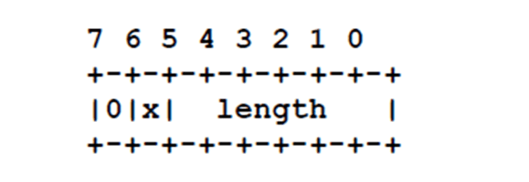
[NTL] defines the type and length of the ATM number immediately following the [STL] field. The format is as follows:
The most significant bit is reserved and MUST be set to zero. The second most significant bit (x) is a flag indicating whether the ATM number is in:
Native E.164 format (x = 1).
The bottom 6 bits represent an unsigned integer value indicating the length of the associated ATM address field in octets.
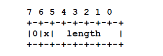
The [STL] format is the same as the [NTL] field. Defines the length of the subaddress field, if it exists. If it does not exist this entire octet field MUST be zero. If the subaddress exists it will be in AESA format, so flag x SHALL be zero.
[NBMA Number] is a variable length field containing the ATM address of the Link layer target. It is always present.
[NBMA Subaddress] is a variable length field containing the ATM subaddress of the Link layer target. It may or may not be present. When it is not, the option ends after the [NBMA Number] (or any additional padding for 8-byte alignment).
The octet ordering of the [NBMA Number] and [NBMA Subaddress] fields SHALL be the same as that used in MARS and NHRP control messages.
4.2 UNI 3.0/3.1 signaling issues (SVC mode).
When an IPv6 node places a call to another IPv6 node, it SHOULD follow the procedures in “ATM Signalling Support for IP over ATM”, RFC 1755, and “Default IP MTU for use over ATM AAL5”, RFC 1626 for signaling UNI 3.0/3.1 SVCs “ATM User Network Interface (UNI) Specification Version 3.1” and negotiating MTU. The default IP MTU size on a LL is 9180 bytes as specified in RFC 1626.
Note that while the procedures in RFC 1626 still apply to IPv6 over ATM, IPv6 Path MTU Discovery RFC 1981 is used by nodes and routers rather than IPv4 MTU discovery. Additionally, while IPv6 nodes are not required to implement Path MTU Discovery, IPv6/ATM nodes SHOULD implement it. Also, since IPv6 nodes will negotiate an appropriate MTU for each VC, Path MTU should never be triggered since neither node should ever receive a Packet Too Big message to trigger Path MTU Discovery. When nodes are communicating via one or more routers Path MTU Discovery will be used just as it is for legacy networks.
5 Interface Tokens
5.1 Interface Tokens Based on ESI values
[0x00] is a one octet field which is always set to 0.
Note that the bit corresponding to the EUI-64 Global/Local bit “64-Bit Global Identifier Format Tutorial” is always reset indicating that this address is not a globally unique IPv6 interface token.
[ESI] is a six octet field.
This field always contains the six octet ESI value for the AESA used to address the specific instance of the IPv6/ATM interface.
[SEL] is a one octet field.
This field always contains the SEL value from the AESA used to address the specific instance of the IPv6/ATM interface.
5.2 Interface Tokens Based on 48 Bit MAC Values
5.3 Interface Tokens Based on EUI-64 Values
Where the underlying ATM NIC driver has access to a set of one or more 64-bit EUI-64 values unique to the ATM NIC (e.g. EUI-64 addresses configured into the NIC’s ROM), the IPv6/ATM interface SHOULD use one of these values to create a unique interface token. after inverting the Global/Local identifier bit RFC 2373. (Any relationship between these values and the ESI(s) registered with the local ATM switch by the ATM driver are outside the scope of this document.)
When EUI-64 values are used for IPv6 interface tokens the only modification allowed to the octet string read from the NIC is an inversion of the Global/Local identifier bit.
5.4 Interface Tokens Based on Native E.164 Addresses
When an interface uses Native E.164 addresses then the E.164 values MAY be used to generate an interface token as follows:
[D14][D13D12][D11D10][D9D8][D9D6][D5D4][D3D2][D1D0]
[D14] A single octet containing the semi-octet representing the most significant E.164 digit shifted left four bits to the most significant four bits of the octet. The lower four bits MUST be set to 0. Note that the EUI-64 Global/Local indicator is set to 0 indicating that this is not a globally unique IPv6 interface token.
[D13D12] A single octet containing the semi-octet representing the second most significant E.164 digit [D13] shifted left four places to the most significant bits of the octet, and the third most significant semi-octet in the four least significant bits of the octet.
[D11D10] – [D1D0] Octets each containing two E.164 digits, one in the most significant four bits, and one in the least significant four bits as indicated.
 |
5.5 Nodes Without Unique Identifiers
5.6 Multiple Logical Links on a Single Interface
A logical ATM interface might be associated with a different SEL field of a common AESA prefix, or a set of entirely separate ESIs might have been registered with the local ATM switch to create a range of unique AESAs.
The minimum information required to uniquely identify each logical ATM interface is (within the context of the local switch port) their ESI+SEL combination.
For the vhost case described in section 5.1.2 of RFC 2491, vhost SHALL select a different interface token from the range of 64-bit values available to the ATM NIC (as described in 4.1). Each vhost SHALL implement IPv6/ATM interfaces in such a way that no two or more vhosts end up advertising the same interface token onto the same LL. (Conformance with this requirement may be achieved by choosing different SEL values, ESI values, or both.)

Books you may interested
 |
 |
 |
