PPP in HDLC-like Framing
Posted on |
PPP in HDLC-like Framing
1. Introduction
This specification provides for framing over both bit-oriented and octet-oriented synchronous links, and asynchronous links with 8 bits of data and no parity. These links MUST be full-duplex but MAY be either dedicated or circuit-switched.
An escape mechanism is specified to allow control data such as XON/XOFF to be transmitted transparently over the link, and to remove spurious control data which may be injected into the link by intervening hardware and software. Some protocols expect error-free transmission, and either provide error detection only on a conditional basis or o not provide it at all. PPP uses the HDLC Frame Check Sequence for error detection. This is commonly available in hardware implementations, and a software implementation is provided.
2. Physical Layer Requirements
Interface Format
Transmission Rate
Control Signals
PPP does not require the use of control signals, such as Request To Send (RTS), Clear To Send (CTS), Data Carrier Detect (DCD), and Data Terminal Ready (DTR).
When available, using such signals can allow greater functionality and performance. In particular, such signals SHOULD be used to signal the Up and Down events in the LCP Option Negotiation Automaton [1]. When such signals are not available, the implementation MUST signal the Up event to LCP upon initialization, and SHOULD NOT signal the Down event.
Because signaling is not required, the physical layer MAY be decoupled from the data link layer, hiding the transient details of the physical transport. This has implications for mobility in cellular radio networks, and other rapidly switching links.
When moving from cell to cell within the same zone, an implementation MAY choose to treat the entire zone as a single link, even though the transmission is switched among several frequencies. The link is considered to be with the central control unit for the zone, rather than the individual cell transceivers. However, the link SHOULD re-establish its configuration whenever the link is switched to a different administration.
Due to the bursty nature of data traffic, some implementations have chosen to disconnect the physical layer during periods of inactivity and reconnect when traffic resumes, without informing the data link layer. Robust implementations should avoid using this trick over-zealously since the price for decreased setup latency is decreased security. Implementations SHOULD signal the Down event whenever “significant time” has elapsed since the link was disconnected. The value for “significant time” is a matter of considerable debate, and is based on the tariffs, call setup times, and security concerns of the installation.
3. The Data Link Layer
PPP uses the principles described in ISO 3309-1979 HDLC frame structure, most recently the fourth edition 3309:1991 [2], which specifies modifications to allow HDLC use in asynchronous environments.
The PPP control procedures use the Control field encodings described in ISO 4335-1979 HDLC elements of procedures, most recently the fourth edition 4335:1991 [4].
This should not be construed to indicate that every feature of the above recommendations is included in PPP. Each feature included is explicitly described in the following sections.
To remain consistent with standard Internet practice, and avoid confusion for people used to reading RFCs, all binary numbers in the following descriptions are in Most Significant Bit to Least Significant Bit order, reading from left to right, unless otherwise indicated. Note that this is contrary to standard ISO and CCITT the practice which orders bits as transmitted (network bit order). Keep this in mind when comparing this document with the international standards documents.
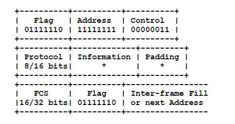
3.1. Frame Format
Flag Sequence
Each frame begins and ends with a Flag Sequence, which is the binary sequence 01111110 (hexadecimal 0x7e). All implementations continuously check for this flag, which is used for frame synchronization.
Only one Flag Sequence is required between two frames. Two consecutive Flag Sequences constitute an empty frame, which is silently discarded, and not counted as a FCS error.
Address Field
The Address field is a single octet, which contains the binary sequence 11111111 (hexadecimal 0xff), the All-Stations address. Individual station addresses are not assigned. The All-Stations address MUST always be recognized and received.
The use of other address lengths and values may be defined at a later time, or by prior agreement. Frames with unrecognized Addresses SHOULD be silently discarded.
Control Field
The Control field is a single octet, which contains the binary sequence 00000011 (hexadecimal 0x03), the Unnumbered Information (UI) command with the Poll/Final (P/F) bit set to zero.
The use of other Control field values may be defined at a later time, or by prior agreement. Frames with unrecognized Control field values SHOULD be silently discarded.
Frame Check Sequence (FCS) Field
The Frame Check Sequence field defaults to 16 bits (two octets). The FCS is transmitted least significant octet first, which contains the coefficient of the highest term.
A 32-bit (four octets) FCS is also defined. Its use may be negotiated as described in “PPP LCP Extensions” [5].
The use of other FCS lengths may be defined at a later time, or by prior agreement.
The FCS field is calculated over all bits of the Address, Control, Protocol, Information and Padding fields, not including any start and stop bits (asynchronous) nor any bits (synchronous) or octets (asynchronous or synchronous) inserted for transparency. This also does not include the Flag Sequences nor the FCS field itself.
When octets are received which are flagged in the Async-Control-Character-Map, they are discarded before calculating the FCS.
For more information on the specification of the FCS, see the Appendices.
3.2. Modification of the Basic Frame
Address-and-Control-Field-Compression
When using the standard HDLC-like framing, the Address and Control fields contain the hexadecimal values 0xff and 0x03 respectively. When other Addresses or Control field values are in use, Address-and-Control-Field-Compression MUST NOT be negotiated.
On transmission, compressed Address and Control fields are simply omitted.
On reception, the Address and Control fields are decompressed by examining the first two octets. If they contain the values 0xff and 0x03, they are assumed to be the Address and Control fields. If not, it is assumed that the fields were compressed and were not transmitted.
By definition, the first octet of a two octet Protocol field will never be 0xff (since it is not even). The Protocol field value 0x00ff is not allowed (reserved) to avoid ambiguity when Protocol-Field-Compression is enabled and the first Information field octet is 0x03.
4. Octet-stuffed framing
4.1. Flag Sequence
4.2. Transparency
An octet stuffing procedure is used. The Control Escape octet is defined as binary 01111101 (hexadecimal 0x7d), most significant bit first.
As a minimum, sending implementations MUST escape the Flag Sequence and Control Escape octets.
After FCS computation, the transmitter examines the entire frame between the two Flag Sequences. Each Flag Sequence, Control Escape octet, and any octet which is flagged in the sending Async-Control-Character-Map (ACCM) is replaced by a two octet sequence consisting of the Control Escape octet followed by the original octet exclusive-or’d with hexadecimal 0x20.
This is bit 5 complemented, where the bit positions are numbered 76543210 (the 6th bit as used in ISO numbered 87654321 — BEWARE when comparing documents).
Receiving implementations MUST correctly process all Control Escape sequences.
On reception, prior to FCS computation, each octet with value less than hexadecimal 0x20 is checked. If it is flagged in the receiving ACCM, it is simply removed (it may have been inserted by intervening data communications equipment). Each Control Escape octet is also removed, and the following octet is exclusive-or’d with hexadecimal 0x20, unless it is the Flag Sequence (which aborts a frame).
A few examples may make this more clear. Escaped data is transmitted on the link as follows:
4.3. Invalid Frames
4.4. Time Fill
4.4.1. Octet-synchronous
The Flag Sequence MUST be transmitted during inter-frame time fill.
4.4.2. Asynchronous
Inter-octet time fill MUST be accomplished by transmitting continuous “1” bits (mark-hold state).
Inter-frame time fill can be viewed as extended inter-octet time fill. Doing so can save one octet for every frame, decreasing delay and increasing bandwidth. This is possible since a Flag Sequence may serve as both a frame end and a frame begin. After having received any frame, an idle receiver will always be in a frame begin state.
Robust transmitters should avoid using this trick over-zealously since the price for the decreased delay is decreased reliability. Noisy links may cause the receiver to receive garbage characters and interpret them as part of an incoming frame. If the transmitter does not send a new opening Flag Sequence before sending the next frame, then that frame will be appended to the noise characters causing an invalid frame (with high reliability).
It is suggested that implementations will achieve the best results by always sending an opening Flag Sequence if the new frame is not back-to-back with the last. Transmitters SHOULD send an open Flag Sequence whenever “appreciable time” has elapsed after the prior closing Flag Sequence. The maximum value for “appreciable time” is likely to be no greater than the typing rate of a slow typist, about 1 second.
4.5. Transmission Considerations
4.5.1. Octet-synchronous
4.5.2. Asynchronous
5. Bit-stuffed framing
5.1. Flag Sequence
The Flag Sequence indicates the beginning or end of a frame and is used for frame synchronization. The bit stream is examined on a bit-by-bit basis for the binary sequence 01111110 (hexadecimal 0x7e).
The “shared zero mode” Flag Sequence “011111101111110” SHOULD NOT be used. When not avoidable, such an implementation MUST ensure that the first Flag Sequence detected (the end of the frame) is promptly communicated to the link layer. Use of the shared zero mode hinders interoperability with bit-synchronous to asynchronous and bit-synchronous to octet-synchronous converters.
5.2. Transparency
After FCS computation, the transmitter examines the entire frame between the two Flag Sequences. A “0” bit is inserted after all sequences of five contiguous “1” bits (including the last 5 bits of the FCS) to ensure that a Flag Sequence is not simulated.
On reception, prior to FCS computation, any “0” bit that directly follows five contiguous “1” bits is discarded.
5.3. Invalid Frames
5.4. Time Fill
There is no provision for inter-octet time fill.
The Flag Sequence SHOULD be transmitted during inter-frame time fill. However, certain types of circuit-switched links require the use of mark idle (continuous ones), particularly those that calculate accounting based on periods of bit activity. When mark idle is used on a bit-synchronous link, the implementation MUST ensure at least 15 consecutive “1” bits between Flags during the idle period, and that the Flag Sequence is always generated at the beginning of a frame after an idle period.
This differs from practice in ISO 3309, which allows 7 to 14-bit mark idle.
5.5. Transmission Considerations
All octets are transmitted least significant bit first.
The definition of various encodings and scrambling is the responsibility of the DTE/DCE equipment in use and is outside the scope of this specification.
While PPP will operate without regard to the underlying representation of the bitstream, lack of standards for transmission will hinder interoperability as surely as lack of data link standards. At speeds of 56 Kbps through 2.0 Mbps, NRZ is currently most widely available, and on that basis is recommended as a default.
When the configuration of the encoding is allowed, NRZI is recommended as an alternative, because of its relative immunity to signal inversion configuration errors, and instances when it MAY allow connection without an expensive DSU/CSU. Unfortunately, NRZI encoding exacerbates the missing x1 factor of the 16-bit FCS, so that one error in 2**15 goes undetected (instead of one in 2**16), and triple errors are not detected. Therefore, when NRZI is in use, it is recommended that the 32-bit FCS be negotiated, which includes the x1 factor.
At higher speeds of up to 45 Mbps, some implementors have chosen the ANSI High-Speed Synchronous Interface [HSSI]. While this experience is currently limited, implementors are encouraged to cooperate in choosing transmission encoding.
6. Asynchronous to Synchronous Conversion
There may be some use of asynchronous-to-synchronous converters (some built into modems and cellular interfaces), resulting in an asynchronous PPP implementation on one end of a link and a synchronous implementation on the other. It is the responsibility of the converter to do all stuffing conversions during operation.
To enable this functionality, synchronous PPP implementations MUST always respond to the Async-Control-Character-Map Configuration Option with the LCP Configure-Ack. However, acceptance of the Configuration Option does not imply that the synchronous implementation will do any ACCM mapping. Instead, all such octet mapping will be performed by the asynchronous-to-synchronous converter.
7. Additional LCP Configuration Options
The Configuration Option format and basic options are already defined for LCP [1].
Up-to-date values of the LCP Option Type field are specified in the most recent “Assigned Numbers” RFC [10]. This document concerns the following values:
7.1. Async-Control-Character-Map (ACCM)
This Configuration Option provides a method to negotiate the use of control character transparency on asynchronous links.
Each end of the asynchronous link maintains two Async-Control-Character-Maps. The receiving ACCM is 32 bits, but the sending ACCM may be up to 256 bits. This results in four distinct ACCMs, two in each direction of the link.
For asynchronous links, the default receiving ACCM is 0xffffffff. The default sending ACCM is 0xffffffff, plus the Control Escape and Flag Sequence characters themselves, plus whatever other outgoing characters are flagged (by prior configuration) as likely to be intercepted.
For other types of links, the default value is 0, since there is no need for mapping.
The default inclusion of all octets less than hexadecimal 0x20 allows all ASCII control characters [6] excluding DEL (Delete) to be transparently communicated through all known data communications equipment.
The transmitter MAY also send octets with values in the range 0x40 through 0xff (except 0x5e) in Control Escape format. Since these octet values are not negotiable, this does not solve the problem of receivers which cannot handle all non-control characters. Also, since the technique does not affect the 8th bit, this does not solve problems for communications links that can send only 7-bit characters.
Note that this specification differs in detail from later amendments, such as 3309:1991/Amendment 2 [3]. However, such “extended transparency” is applied only by “prior agreement”. Use of the transparency methods in this specification constitutes a prior agreement with respect to PPP.
For compatibility with 3309:1991/Amendment 2, the transmitter MAY escape DEL and ACCM equivalents with the 8th (most significant) bit set. No change is required in the receiving algorithm.
Following ACCM negotiation, the transmitter SHOULD cease escaping DEL.
However, it is rarely necessary to map all control characters, and often it is unnecessary to map any control characters. The Configuration Option is used to inform the peer which control characters MUST remain mapped when the peer sends them.
The peer MAY still send any other octets in mapped format if it is necessary because of constraints are known to the peer. The peer SHOULD Configure-Nak with the logical union of the sets of mapped octets so that when such octets are spuriously introduced they can be ignored on receipt.
A summary of the Async-Control-Character-Map Configuration Option format is shown below. The fields are transmitted from left to right.
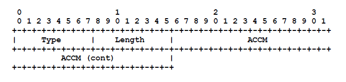
The ACCM field is four octets and indicates the set of control characters to be mapped. The map is sent most significant octet first.
Each numbered bit corresponds to the octet of the same value. If the bit is cleared to zero, then that octet need not be mapped. If the bit is set to one, then that octet MUST remain mapped. For example, if bit 19 is set to zero, then the ASCII control character 19 (DC3, Control-S) MAY be sent in the clear.
Note: The least significant bit of the least significant octet (the final octet transmitted) is numbered bit 0, and would map to the ASCII control character NUL.
A. Recommended LCP Options
High-Speed links
Low Speed or Asynchronous links
B. Automatic Recognition of PPP Frames
Note that the first two forms are not a valid username for Unix. However, only the third form generates a correctly checksummed PPP frame, whenever 03 and ff are taken as the control characters ETX and DEL without regard to parity (they are correct for an even parity link) and discarded.
Many implementations deal with this by putting the interface into packet mode when one of the above username patterns are detected during login, without examining the initial PPP checksum. The initial incoming PPP frame is discarded, but a Configure-Request is sent immediately.
C. Fast Frame Check Sequence (FCS) Implementation
The FCS was originally designed with hardware implementations in mind. A serial bit stream is transmitted on the wire, the FCS is calculated over the serial data as it goes out, and the complement of the resulting FCS is appended to the serial stream, followed by the Flag Sequence.
The receiver has no way of determining that it has finished calculating the received FCS until it detects the Flag Sequence. Therefore, the FCS was designed so that a particular pattern results when the FCS operation passes over the complemented FCS. A good frame is indicated by this “good FCS” value.
C.1. FCS table generator
C.2. 16-bit FCS Computation Method
C.3. 32-bit FCS Computation Method
 |  |  |  |  |  |
