ATM Signaling Support for IP over ATM
Posted on |
ATM Signaling Support for IP over ATM
1. Abstract
This memo describes the ATM call control signaling exchanges needed to support Classical IP over ATM implementations as described in RFC 1577 [LAUB94]. ATM endpoints will incorporate ATM signaling services as specified in the ATM Forum User-Network Interface (UNI) Specification Version 3.1 [ATMF94]. IP over ATM implementations utilize the services of local ATM signaling entities to establish and release ATM connections. This memo should be used to define the support required by IP over ATM implementations from their local ATM signaling entities.
This document is an implementor’s guide intended to foster interoperability among RFC 1577, RFC 1483, and UNI ATM signaling. It applies to IP hosts and routers which are also ATM end systems and assumes ATM networks that completely implement the ATM Forum UNI Specification Version 3.1. Unless explicitly stated, no distinction is made between the Private and Public UNI.
UNI 3.1 is considered an erratum to the UNI 3.0 specification. It has been produced by the ATM Forum, largely for reasons of alignment with Recommendation Q.2931. Although UNI 3.1 is based on UNI 3.0 there are several changes that make the two versions incompatible. A description of how to support IP over ATM using UNI 3.0 is found in Appendix B.
2. Overview
In a Switched Virtual Connection (SVC) environment, ATM virtual channel connections (VCCs) are dynamically established and released as needed. This is accomplished using the ATM call/connection control signaling protocol, which operates between ATM end-systems and the ATM network. The signaling entities use the signaling protocol to establish and release calls (association between ATM endpoints) and connections (VCCs). Signaling procedures include the use of addressing to locate ATM endpoints and allocation of resource in the network for the connection. It also provides indication and negotiation between ATM endpoints for selection of end-to-end protocols and their parameters. This memo describes how the signaling protocol is used in support of IP over ATM, and, in particular, the information exchanged in the signaling protocol to effect this support.
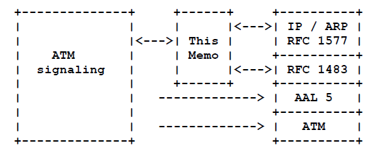
IP address to ATM address resolution and routing issues are not in the scope of this memo, and are treated as part of IP in figure 1.
Relationship of this memo to IP, RFC 1483, ATM signaling, ATM and AAL53. Use of Protocol Procedures
3.1. VC Establishment
The owner of an existing VCC is defined to be the entity within the ATM end-system that establishes the connection. An ATM end-system MAY establish an ATM call when it has a datagram to send and either there is no existing VCC that it can use for this purpose, it chooses not to use an existing VCC, (e.g., for reasons of route optimization or quality of service), or the VCC owner does not allow sharing.
To reduce the latency of the address resolution procedure at the called station, the following procedure MAY be used:
If a VCC is established using the LLC/SNAP encapsulation, the calling endstation of the VCC MAY send an InARP_REQUEST to the called endstation after the connection is established (i.e. received a CONNECT message) and before the calling endstation sends the first data packet. In addition, the calling endstation MAY send its data packets without waiting for the InARP_REPLY. An endstation MAY respond, generate, and manage its ATMARP table according to the procedures specified in RFC1293 [BRAD92], Section 7, “Protocol Operation”, during the life time of the VCC.
To avoid establishing multiple VCCs to the same endstation, a called endstation MAY associate the calling party number in the SETUP message with the established VCC. This VCC MAY be used to transmit data packets destined to an endstation whose ATMARP resolution results in an ATM address that is the same as the associated calling party number. Sharing of VCCs is subject to the policies configured at the endstation as described in section 4.3 of this recommendation.
3.2. Multiprotocol Support on VCs
3.3. Support for Multiple VCs
An ATMARP server or client MAY establish an ATM call when it has a datagram to send and either there is no existing VCC that it can use for this purpose, it chooses not to use an existing VCC, or the owner of the VCC does not allow sharing. Note that there might be VCCs to the destination which are used for IP, but an ARP server might prefer to use a separate VCC for ARP only. The ATMARP server or client MAY maintain or release the call as specified in RFC 1577. However, if the VCC is shared among several protocol entities, the ATMARP client or server SHALL NOT disconnect the call as suggested in RFC 1577.
Systems MUST be able to support multiple connections between peer systems (without regard to which peer system initiated each connection). They MAY be configured to only allow one such connection at a time.
If a receiver accepts more than one call from a single source, that receiver MUST then accept incoming PDUs on the additional connection(s) and MAY transmit on the additional connections. Receivers SHOULD NOT accept the incoming call, only to close the connection or ignore PDUs from the connection.
Because opening multiple connections are specifically allowed, algorithms to prevent connection call collision, such as the one found in section 8.4.3.5 of ISO/IEC 8473 [ISO8473], MUST NOT be implemented.
While allowing multiple connections is specifically desired and allowed, implementations MAY choose (by configuration) to permit only a single connection to some destinations. Only in such a case, if a colliding incoming call is received while a call request is pending, the incoming call MUST be rejected. Note that this MAY result in a failure to establish a connection. In such a case, each system MUST wait for at least a configurable collision retry time in the range 1 to 10 seconds before retrying. Systems MUST add a random increment, with exponential backoff.
3.4. VC Teardown
Either end-system close a connection. If the connection is closed or reset while a datagram is being transmitted, the datagram is lost. Systems SHOULD be able to configure a minimum holding time for connections to remain open as long as the endpoints are up. (Note that holding time, the time the connection has been open, differs from idle time.) A suggested default value for the minimum holding time is 60 seconds.
Because some public networks MAY charge for connection holding time, and connections MAY be a scarce resource in some networks or end-systems, each system implementing a Public ATM UNI interface MUST support the use of a configurable inactivity timer to clear connections that are idle for some period of time. The timer’s range SHOULD include a range from a small number of minutes to “infinite”. A default value of 20 minutes is RECOMMENDED. Systems which only implement a Private ATM UNI interface SHOULD support the inactivity timer. If implemented, the inactivity timer MUST monitor traffic in both directions of the connection.
4. Brief Overview of UNI Call Setup Signaling Procedures and Messages
This section provides a summary of point-to-point signaling procedures. Readers are referred to [ATMF93].
UNI signaling messages used for point-to-point call/connection control are the following:
5. Overview of Call Establishment Message Content
Signaling messages are structured to contain mandatory and optional variable length information elements (IEs). IEs are further subdivided into octet groups, which in turn are divided into fields. IEs contain information related to the call, which is relevant to the network, the peer endpoint or both. Selection of optional IEs and the content of mandatory and optional IEs in a call establishment message determines the parties to and nature of the communication over the ATM connection. For example, the call establishment message for a call which will be used for constant bitrate video over AAL 1 will have different contents than a call which will be used for IP over AAL 5.
A SETUP message which establishes an ATM connection to be used for IP and multiprotocol interconnection calls MUST contain the following IEs:
6. Information Elements with Endpoint to Endpoint Significance
6.1. ATM Adaptation Layer Parameters
The AAL Parameters IE (see section 5.4.5.5 and Annex F of [ATMF93]) carries information about the ATM Adaptation Layer (AAL) to be used on the connection. RFC 1483 specifies encapsulation of IP over AAL 5. Thus, AAL 5 MUST be indicated in the “AAL type” field.
Coding and procedure related to the ‘Forward and Backward Maximum CPCS-SDU Size’ fields are discussed in [ATKI94]. Values may range from zero to 65,535. Although the default IP over AAL 5/ATM is 9188 bytes, endstations are encouraged to support MTU sizes up to and including 64k.
Ordinarily, no Service Specific Convergence Sublayer (SSCS) will be used for multiprotocol interconnect over AAL5. Therefore, the SSCS ‘type’ field SHOULD be absent or, if present, coded to Null SSCS.
Format and field values of AAL Parameters IE

6.2. Broadband Low Layer Information
Selection of an encapsulation to support IP over an ATM VCC is done using the Broadband Low Layer Information (B-LLI) IE, along with the AAL Parameters IE, and the B-LLI negotiation procedure.
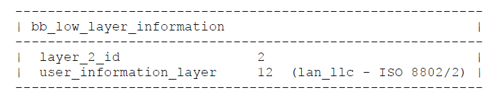
RFC 1577 specifies LLC/SNAP as the default encapsulation. This encapsulation MUST be implemented by all endstations. LLC encapsulation MUST be signaled in the B-LLI as shown below. Signaling indication of other encapsulations is discussed in Appendix D, Section 4. Note that only LLC is indicated in the B-LLI. It is up to the LLC layer to look into the encapsulation header of the packets following call setup. A B-LLI specifying both LLC and a layer_3_id SNAP layer is not recommended. If in those packets, the SNAP header indicates IP, it is the LLC layer’s job to hand the packets up to IP.
Format of B-LLI IE indicating LLC/SNAP encapsulation
 6.2.1. Framework for Protocol Layering
 6.2.1. Framework for Protocol Layering
The support of connectionless services from a connection-oriented link layer exposes general problems of connection management, specifically the problems of connection acceptance, assignment of quality of service, and connection shutdown. For a connection to be associated with the correct protocol on the called host, it is necessary for information about one or more layers of protocol identification to be associated with a connection “management entity” or “endpoint”. This association is what we call a binding in this memo. In this section, we attempt to describe a framework for a usable binding or service architecture given the available IEs in the ATM call control messages.
It is important to distinguish between two basic uses of protocol identification elements present in the UNI setup message. The first is the description of the protocol encapsulation that will be used on the data packet over the virtual connection, the second is the entity that will be responsible for managing the call. All protocols present in various IEs MUST be used to encapsulate the call, but the most specific, or highest, layer specified SHOULD manage the call. This defines a hierarchy of services and provides a framework for applications, including LLC and IP, to terminate calls. This hierarchy provides a clear mechanism for support of higher level protocol and application bindings when their use and specification is defined in the appropriate standards bodies.
In general, it would be desirable to allow data packets to be stored directly into an application’s address space after the connection is established. This is possible only if we have both encapsulation and managing entity indications in the signaling message.
The B-LLI is the only information element currently available in UNI 3.1 for designating protocol endpoints. It contains codepoints that describe layer 2 and layer 3 protocol entities associated with the call. There are other information elements under consideration in the ATM Forum and ITU, which could come to play a significant role in the description of the application to connection binding, but their use is not yet defined, and they are not part of the framework described in RFC 1577. They include B-HLI, for containing information for a higher layer protocol, Network Layer Information (NLI) to contain information for the network layer, and UUI, which is meant to carry information for use by the top level application.
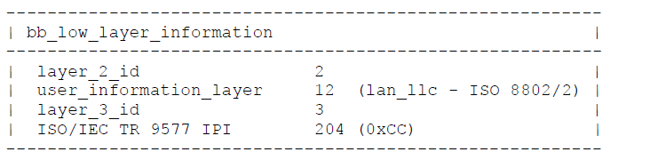
The following figure shows a B-LLI that MAY be used for specifying in call setup that IP will manage the call and that this VC will be used only for IP traffic. Called parties MUST accept this B-LLI. The caller using VC MUST use LLC-SNAP encapsulation on all IP datagrams, despite the fact that the caller views the VC as dedicated to IP. The reason for this requirement is that while we require receivers to accept this form of call setup, they may choose whether or not to multiplex the call through LLC, in other words, to ignore the Layer 3 information. This choice is dependent on the receiver’s implementation’s protocol architecture and is local to the receiver.
The format of B-LLI IE indicating VC ownership by IP NOTE: LLC/SNAP encapsulation is still used)
 Null-encapsulated VCs are described in RFC 1483. Such a VC would result in the most direct form of binding a VC to IP. However, the method of signaling for this type of VC has not yet been integrated into the IP over ATM context. For completeness, we mention that the signaling would use a B-LLI containing the layer 3 identifier with the ISO/IEC TR-9577 protocol codepoint and omitting the layer 2 identifier [ATMF93]. Since no layer 2 is specified, frames produced by AAL processing would be given directly to IP. Processing of this B-LLI is not required at this time.
7. Information Elements with Significance to the ATM Network
This section describes the coding of, and procedures surrounding, information elements with significance to the ATM network, as well as the endpoints of an ATM call supporting multiprotocol operation.
The standards, implementation agreements, research and experience surrounding such issues as traffic management, quality of service and bearer service description are still evolving. Much of this material is cast to give the greatest possible latitude to ATM network implementation and service offerings. ATM end-systems need to match the traffic contract and bearer service they request from the network to the capabilities offered by the network. Therefore, this memo can only offer what, at the present time, are the most appropriate and efficient coding rules to follow for setting up IP and ATMARP VCCs. Future revisions of this memo may take advantage of ATM services and capabilities that are not yet available.
7.1. ATM Traffic Descriptor
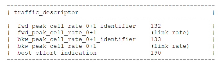
The ATM traffic descriptor characterizes the ATM virtual connection in terms of peak cell rate (PCR), sustainable cell rate (SCR), and maximum burst size. This information is used to allocate resources (e.g., bandwidth, buffering) in the network. In general, the ATM traffic descriptor for supporting multiprotocol interconnection over ATM will be driven by factors such as the capacity of the network, conformance definition supported by the network, performance of the ATM end system and (for public networks) cost of services.
The most convenient model of IP behavior corresponds to the Best Effort Capability (see section 3.6.2.4 of [ATMF93]). If this capability is offered by the ATM network(s), it MAY be requested by including the Best Effort Indicator, the peak cell rate forward (CLP=0+1) and peak cell rate backward (CLP=0+1) fields in the ATM Traffic Descriptor IE. When the Best Effort Capability is used, no guarantees are provided by the network, and in fact, throughput may be zero at any time. This type of behavior is also described by RFC 1633 [BRAD94].
When the network does not support Best Effort Capability or more predictable ATM service is desired for IP, more specific traffic parameters MAY be specified and the Best Effort capability not used. Doing so includes the use of two other traffic-related IEs and is discussed in the following paragraphs and sections.
The Traffic Descriptor IE is accompanied by the Broadband Bearer Capability IE and the QoS Parameter IE. Together these define the signaling view of ATM traffic management. In this memo, we present an agreed-on, required subset of traffic management capabilities, as specified by using the three IEs. The figure immediately below shows the set of the allowable combinations of traffic parameters which all IP over ATM end-systems MUST support in their ATM signaling. The subset includes Best Effort in the form of a non-guaranteed bitrate combination (the rightmost column of the table below); a type of traffic description that is intended for ATM “pipes”, for example between two routers (the middle column); and a type of traffic the description that will allow initial use of token-bucket style characterizations of the source, as presented in RFC 1363 [PART92] and RFC 1633, for example (the leftmost column).
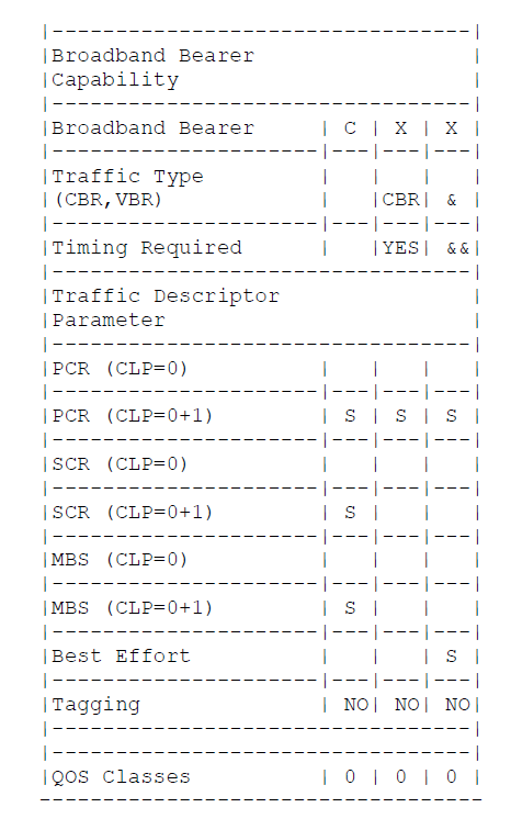 S = Specified
Use of other allowable combinations of traffic parameters listed in the large table in Appendix C may work since they are allowed by [ATMF94], but this will depend on the calling end-system, the network, and the called end send system.
If Best Effort service is not used, link rate SHOULD not be requested as the peak cell rate. Without any knowledge of the application, it is RECOMMENDED that a fraction, such as 1/10th, of the link bandwidth, be requested.
[ATMF93] does not provide any capability for negotiation of the ATM traffic descriptor parameters. This means that:
- the calling end system SHOULD have some prior knowledge as to the traffic contract that will be acceptable to both the called end system and the network.
- if, in response to a SETUP message, a calling end system receive a RELEASE COMPLETE message, or a CALL PROCEEDING message followed by a RELEASE COMPLETE message, with cause #37, User Cell Rate Unavailable, it MAY examine the diagnostic field of the Cause IE and reattempt the call after selecting smaller values for the parameter(s) indicated. If the RELEASE COMPLETE or RELEASE message is received with cause #73, an Unsupported combination of traffic parameter, it MAY try other combinations from table 5-7 and 5-8 of [ATMF93].
- the called end system SHOULD examine the ATM traffic descriptor IE in the SETUP message. If it is unable to process cells at the Forward PCR indicated, it SHOULD clear the call with cause #37, User Cell Rate Unavailable.
7.2. Broadband Bearer Capability
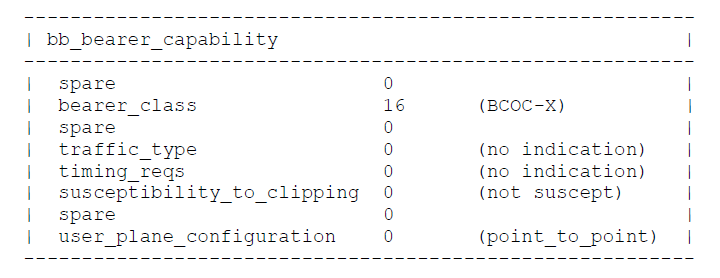
IP over ATM signaling MUST permit BCOB-C and BCOB-X, in the combinations shown in the previous section. It MAY also permit one of the allowable combinations shown in Appendix C.
Currently, there is no capability for negotiation of the broadband bearer capability. This means that:
- the calling end system SHOULD have some prior knowledge as to the broadband bearer capability that will be acceptable to both the called end system and the network.
- if in response to a SETUP message, a calling end system receives a RELEASE COMPLETE message, or a CALL PROCEEDING message followed by a RELEASE COMPLETE message, with cause #57, bearer capability not authorized or #58 bearer capability not presently available, it MAY reattempt the call after selecting another bearer capability.
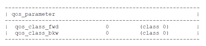
7.3. QoS Parameter
The Unspecified QoS class (Class 0) is the only QoS class that must be supported by all networks and the only QoS class allowed when using the Best Effort service. The Specified QoS Class for Connection Oriented Data Transfer (Class 3) or the Specified QoS Class for Connectionless Data Transfer (Class 4) may be applicable to multiprotocol over ATM, but their use has to be negotiated with the network provider. The combinations of QoS parameters with the ATM Traffic Descriptor and the Broadband Bearer Capability are detailed in the Traffic Descriptor section and in Appendix C.
Format and field values of QoS Parameters IE
- the calling end system SHOULD have some prior knowledge as to the QoS classes offered by the ATM network in conjunction with the requested Broadband Bearer Service and Traffic Descriptor.
- if in response to a SETUP message, a calling end system receives a RELEASE COMPLETE message, or a CALL PROCEEDING message followed by a RELEASE COMPLETE message, with cause #49, Quality of Service Unavailable, it MAY reattempt the call after selecting another QoS class.
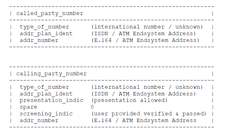
7.4. ATM Addressing Information
ATM addressing information is carried in the Called Party Number, Calling Party Number, and, under certain circumstance, Called Party Subaddress, and Calling Party Subaddress IE. Section 5.8 of [ATMF93] provides the procedure for an ATM end-system to learn its own ATM address from the ATM network, for use in populating the Calling Party Number IE. Section 5.4.5.14 [ATMF94] describes the syntax and semantics of the calling party subaddress IE.
RFC 1577 RECOMMENDS that a router be able to provide multiple LIS support with a single physical ATM interface that may have one or more individual ATM end system addresses. Use of the Selector field in the NSAPAs and E.164 addresses (in the NSAP format) is identified as a way to differentiate up to 256 different LISs for the same ESI. Therefore, an IP router MAY associate the IP addresses of the various LISs it supports with distinct ATM addresses differentiated only by the SEL field. If an IP router does this association, then its signaling entity MUST carry in the SETUP message the ATM addresses corresponding to the particular IP entity requesting the call, and the IP entity it is requesting a call to. These ATM addresses are carried in the Calling and Called Party Number IEs respectively. Native E.164 addresses do not support an SEL field. For IP routers residing in a Public UNI where native E.164 addresses are used, it is RECOMMENDED that multiple E.164 addresses be used to support multiple LISs. Note: multiple LIS support is the only recommended use of the SEL field. Use of this field is not recommended for selection of higher-level applications.
Resolution of IP addresses to ATM addresses is required of hosts and routers which are ATM end systems that use ATM SVCs. RFC 1577 provides a mechanism for doing IP to ATM address resolution in the classical IP model.
8. Dealing with Failure of Call Establishment
9. Security Considerations
REFERENCES
Books you may interested
 |  |  |  |  |  |
