Classical IP and ARP over ATM
Posted on |
Classical IP and ARP over ATM
2. INTRODUCTION
This memo specifies the stable foundation baseline operational model which will always be available in IP and ARP over ATM implementations. Subsequent memos will build upon and refine this model. However, in the absence or failure of those extensions, operations will default to the specifications contained in this memo. Consequently, this memo will not reference these other extensions. This memo defines only the operation of IP and address resolution over ATM, and is not meant to describe the operation of ATM networks.Any reference to virtual connections, permanent virtual connections, or switched virtual connections applies only to virtual channel onnections used to support IP and address resolution over ATM, and thus are assumed to be using AAL5. This memo places no restrictions or requirements on virtual connections used for other purposes.Initial deployment of ATM provides a LAN segment replacement for:
NOTE: In 1), local IP routers with one or more ATM interfaces will be able to connect islands of ATM networks. In 3), public or private ATM Wide Area networks will be used to connect IP routers, which in turn may or may not connect to local ATM networks. ATM WANs and LANs may be interconnected.
Private ATM networks (local or wide area) will use the private ATM address structure specified in the ATM Forum UNI 3.1 specification [9] or as in the ATM Forum UNI 4.0 specification [19]. This structure is modeled after the format of an OSI Network Service Access Point Address (NSAPA). A private ATM address uniquely identifies an ATM endpoint.
Public networks will use either the address structure specified in ITU-TS recommendation E.164 or the private network ATM address structure. An E.164 address uniquely identifies an interface to a public network.
The characteristics and features of ATM networks are different than those found in LANs:
- ATM provides a Virtual Connection (VC) switched environment. VC setup may be done on either a Permanent Virtual Connection (PVC) or dynamic Switched Virtual Connection (SVC) basis. SVC call management signaling is performed via implementations of the UNI 3.1 protocol [7,9].
- Data to be passed by a VC is segmented into 53 octet quantities called cells (5 octets of ATM header and 48 octets of data)
- The function of mapping user Protocol Data Units (PDUs) into the information field of the ATM cell and vice versa is performed in the ATM Adaptation Layer (AAL). When a VC is created a specific AAL type is associated with the VC. There are four different AAL types, which are referred to individually as “AAL1”, “AAL2”, “AAL3/4”, and “AAL5”. (NOTE: this memo concerns itself with the mapping of IP and ATMARP over AAL5 only. The other AAL types are mentioned for introductory purposes only.) The AAL type is known by the VC endpoints via the call setup mechanism and is not carried in the ATM cell header. For PVCs, the AAL type is administratively configured at the endpoints when the Connection (circuit) is set up. For SVCs, the AAL type is communicated along the VC path via UNI 3.1 as part of call setup establishment and the endpoints use the signaled information for configuration. ATM switches generally do not care about the AAL type of VCs. The AAL5 format specifies a packet format with a maximum size of (64K – 1) octets of user data. Cells for an AAL5 PDU are transmitted first to last, the last cell indicating the end of the PDU. ATM standards guarantee that on a given VC, cell ordering is preserved end-to-end. NOTE: AAL5 provides a non-assured data transfer service – it is up to higher-level protocols to provide retransmission.
- ATM Forum signaling defines point-to-point and point-to-point Connection setup [9, 19.] Multipoint-to-multipoint not yet specified by ITU-TS or ATM Forum.
An ATM Forum ATM address is either encoded as a NSAP form ATM End System Address (AESA) or is an E.164 Public-UNI address [9, 19]. In some cases, both an AESA and an E.164 Public UNI address are needed by an ATMARP client to reach another host or router.
Since the use of AESAs and E.164 public UNI addresses by ATMARP are analogous to the use of Ethernet addresses, the notion of “hardware address” is extended to encompass ATM addresses in the context of ATMARP, even though ATM addresses need not have hardware significance. ATM Forum NSAP format addresses (AESA) use the same basic format as U.S. GOSIP OSI NSAPAs [11].
NOTE: ATM Forum addresses should not be construed as being U.S. GOSIP NSAPAs. They are not, the administration is different, which fields get filled out are different, etc. However, in this document, these will be referred to as NSAPAs.
This memo describes the initial deployment of ATM within “classical” IP networks as a direct replacement for local area networks (Ethernets) and for IP links which interconnect routers, either within or between administrative domains. The “classical” model here refers to the treatment of the ATM host adapter as a networking interface to the IP protocol stack operating in a LAN-based paradigm.
Characteristics of the classical model are:
- The same maximum transmission unit (MTU) size is the default for all VCs in an LIS. However, on a VC-by-VC point-to-point basis, the MTU size may be negotiated during connection setup using Path MTU Discovery to better suit the needs of the cooperating pair of IP members or the attributes of the communications path. (Refer to Section 7.3)
- Default LLC/SNAP encapsulation of IP packets.
- End-to-end IP routing architecture stays the same.
- IP addresses are resolved to ATM addresses by use of an ATMARP service within the LIS – ATMARPs stay within the LIS. From a client’s perspective, the ATMARP architecture stays faithful to the basic ARP model presented in [3].
- One IP subnet is used for many hosts and routers. Each VC directly connects two IP members within the same LIS.
Future memos will describe the operation of IP over ATM when ATM networks become globally deployed and interconnected.
The deployment of ATM into the Internet community is just beginning and will take many years to complete. During the early part of this period, we expect deployment to follow traditional IP subnet boundaries for the following reasons:
- Administrators and managers of IP subnetworks will tend to initially follow the same models as they currently have deployed. The mindset of the community will change slowly over time as ATM increases its coverage and builds its credibility.
- Policy administration practices rely on the security, access, routing, and filtering capability of IP Internet gateways: i.e., firewalls. ATM will not be allowed to “back-door” around these mechanisms until ATM provides better management capability than the existing services and practices.
- Standards for global IP over ATM will take some time to complete and deploy.
This memo details the treatment of the classical model of IP and ATMARP over ATM. This memo does not preclude the subsequent treatment of ATM networks within the IP framework as ATM becomes globally deployed and interconnected; this will be the subject of future documents. This memo does not address issues related to transparent data link layer interoperability.
3. IP SUBNETWORK CONFIGURATION
In the LIS scenario, each separate administrative entity configures its hosts and routers within an LIS. Each LIS operates and communicates independently of other LISs on the same ATM network.
In the classical model, hosts communicate directly via ATM to other hosts within the same LIS using the ATMARP service as the mechanism for resolving target IP addresses to target ATM endpoint addresses. The ATMARP service has LIS scope only and serves all hosts in the LIS. Communication to hosts located outside of the local LIS is provided via an IP router. This router is an ATM endpoint attached to the ATM network that is configured as a member of one or more LISs. This configuration MAY result in a number of disjoint LISs operating over the same ATM network. Using these model hosts of differing IP subnets MUST communicate via an intermediate IP router even though it may be possible to open a direct VC between the two IP members over the ATM network.
By default, the ATMARP service and the classical LIS routing model MUST be available to any IP member client in the LIS.
3.2 LIS Configuration Requirements
- All members of the LIS have the same IP network/subnet number and address mask [8].
- All members withina LIS are directly connected to the ATM network.
- All members of a LIS MUST have a mechanism for resolving IP addresses to ATM addresses via ATMARP (based on [3]) and vice versa via InATMARP (based on [12]) when using SVCs. Refer to Section 8 “LIS ADDRESS RESOLUTION SERVICES” in this memo.
- All members of a LIS MUST have a mechanism for resolving VCs to IP addresses via InATMARP (based on [12]) when using PVCs. Refer to Section 8 “LIS ADDRESS RESOLUTION SERVICES” in this memo.
- All members withina LIS MUST be able to communicate via ATM with all other members in the same LIS; i.e., the Virtual Connection topology underlying the intercommunication among the members is fully meshed.
The following list identifies the set of ATM-specific parameters that MUST be implemented in each IP station connected to the ATM network:
- ATM Hardware Address (atm$ha). The ATM address of the individual IP station.
- ATMARP Request Address list (atm$arp-req-list): atm$arp-req-list is a list containing one or more ATM addresses of individual ATMARP servers located within the LIS. In an SVC environment, ATMARP servers are used to resolve to target IP addresses to target ATM address via an ATMARP request and reply protocol. ATMARP servers MUST have authoritative responsibility for resolving ATMARP requests of all IP members using SVCs located within the LIS.
An LIS MUST have a single ATMARP service entry configured and available to all members of the LIS who use SVCs.
In the case where there is only a single ATMARP server within the LIS, then all ATMARP clients MUST be configured identically to have only one non-null entry in atm$arp-req-list configured with the same address of the single ATMARP service.
If the IP member is operating with PVCs only, then atm$arp-req-list MUST be configured with all null entries and the client MUST not make queries to either address resolution service.
Within the restrictions mentioned above and in Section 8, local administration MUST decide which server address(es) are appropriate for atm$arp-req-list.
By default, atm$arp-req-list MUST be configured using the MIB [18].
Manual configuration of the addresses and address lists presented in this section is implementation dependent and beyond the scope of this document; i.e., this memo does not require any specific configuration method. This memo does require that these addresses MUST be configured completely on the client, as appropriate for the LIS, prior to use by any service or operation detailed in this memo.
3.3 LIS Router Additional Configuration
4. IP PACKET FORMAT
Implementations MUST support IEEE 802.2 LLC/SNAP encapsulation as described in [2]. LLC/SNAP encapsulation is the default packet format for IP datagrams.
This memo recognizes that other encapsulation methods may be used however, in the absence of other knowledge or agreement, LLC/SNAP encapsulation is the default.
This memo recognizes that end-to-end signaling within ATM may allow n negotiation of encapsulation method on a per-VC basis.
5. DEFAULT VALUE FOR IP MTU OVER ATM AAL5
Protocols in wide use throughout the Internet, such as the Network File System (NFS), currently use large frame sizes (e.g., 8 KB). Empirical evidence with various applications over the Transmission Control Protocol (TCP) indicates that larger Maximum Transmission Unit (MTU) sizes for the Internet Protocol (IP) tend to give better performance. Fragmentation of IP datagrams is known to be highly undesirable [16]. It is desirable to reduce fragmentation in the network and thereby enhance performance by having the IP Maximum Transmission Unit (MTU) for AAL5 be reasonably large. NFS defaults to an 8192-byte frame size. Allowing for RPC/XDR, UDP, IP, and LLC headers, NFS would prefer a default MTU of at least 8300 octets. Routers can sometimes perform better with larger packet sizes because most of the performance costs in routers relate to “packets handled” rather than “bytes transferred”. So, there are a number of good reasons to have a reasonably large default MTU value for IP over ATM AAL5.
RFC 1209 specifies the IP MTU over SMDS to be 9180 octets, which is larger than 8300 octets but still in the same range [1]. There is no good reason for the default MTU of IP over ATM AAL5 to be different from IP over SMDS, given that they will be the same magnitude. Having the two be the same size will be helpful in interoperability and will also help reduce the incidence of IP fragmentation.
Therefore, the default IP MTU for use with ATM AAL5 shall be 9180 octets. All implementations compliant and conformant with this specification shall support at least the default IP MTU value for use over ATM AAL5.
5.1 Permanent Virtual Circuits
5.2 Switched Virtual Circuits
Implementations that support Switched Virtual Circuits (SVCs) MUST attempt to negotiate the AAL CPCS-SDU size using the ATM signaling protocol. The industry standard ATM signaling protocol uses two different parts of the Information Element named “AAL Parameters” to exchange information on the MTU over the ATM circuit being set up [9]. The Forward Maximum CPCS-SDU Size field contains the value over the path from the calling party to the called party. The Backwards Maximum CPCS-SDU Size Identifier field contains the value over the path from the called party to the calling party. The ATM Forum specifies the valid values of this identifier as 1 to 65535 inclusive. Note that the ATM Forum’s User-to-Network-Interface (UNI) signaling permits the MTU in one direction to be different from the MTU in the opposite direction, so the Forward Maximum CPCS-SDU Size Identifier might have a different value from the Backwards Maximum CPCS-SDU Size Identifier on the same connection.
If the calling party wishes to use the default MTU it shall still include the “AAL Parameters” information element with the default values for the Maximum CPCS-SDU Size as part of the SETUP message of the ATM signaling protocol [9]. If the calling party desires to use a different value than the default, it shall include the “AAL Parameters” information element with the desired value for the Maximum CPCS-SDU Size as part of the SETUP message of the ATM Signalling Protocol. The called party will respond using the same information elements and identifiers in its CONNECT message response [9].
If the called party receives a SETUP message containing the “Maximum CPCS-SDU Size” in the AAL Parameters information element, it shall handle the Forward and Backward Maximum CPCS-SDU Size Identifier as follows:
- If it is able to accept the ATM MTU values proposed by the SETUP message, it shall include an AAL Parameters information element in its response. The Forward and Backwards Maximum CPCS-SDU Size fields shall be present and their values shall be equal to the corresponding values in the SETUP message.
- If it wishes a smaller ATM MTU size than that proposed, then it shall set the values of the Maximum CPCS-SDU Size in the AAL Parameters information elements equal to the desired value in the CONNECT message responding to the original SETUP message.
- If the calling endpoint receives a CONNECT message that does not contain the AAL Parameters Information Element, but the corresponding SETUP message did contain the AAL Parameters information element (including the forward and backward CPCS-SDU Size fields), it shall clear the call with cause “AAL Parameters cannot be supported”.
- If either endpoint receives a STATUS message with cause “Information Element Non-existent or Not Implemented” or cause “Access Information Discarded”, and with a diagnostic field indicating the AAL Parameters Information Element identifier, it shall clear the call with cause “AAL Parameters cannot be supported.”
- If either endpoint receives CPCS-SDUs in excess of the negotiated MTU size, it may use IP fragmentation or may clear the call with cause “AAL Parameters cannot be supported”. In this case, an error has occurred either due to a fault in an end system or in the ATM network. The error should be noted by ATM network management for human examination and intervention.
5.3 Path MTU Discovery Required
The Path MTU Discovery mechanism is Internet Standard RFC 1191 [17] and is an important mechanism for reducing IP fragmentation on the Internet. This mechanism is particularly important because new subnet ATM uses a default MTU sizes significantly different from older subnet technologies such as Ethernet and FDDI.
In order to ensure good performance throughout the Internet and also to permit IP to take full advantage of the potentially larger IP datagram sizes supported by ATM, all router implementations that comply or conform with this specification must also implement the IP Path MTU Discovery mechanism as defined in RFC 1191 and clarified by RFC 1435 [14]. Host implementations should implement the IP Path MTU Discovery mechanism as defined in RFC 1191.
6. LIS ADDRESS RESOLUTION SERVICES
6.1 ATM-based ARP and InARP Equivalent Services
6.2 Permanent Virtual Connections
An IP station MUST have a mechanism (e.g., manual configuration) for determining what PVCs it has, and in particular which PVCs are being used with LLC/SNAP encapsulation. The details of the mechanism are beyond the scope of this memo.
All IP members supporting PVCs are required to use the Inverse ATM Address Resolution Protocol (InATMARP) (refer to [12]) on those VCs using LLC/SNAP encapsulation. In a strict PVC environment, the receiver SHALL infer the relevant VC from the VC on which the InATMARP_Request or response InATMARP_Reply was received. When the ATM source and/or target address is unknown, the corresponding ATM address length in the InATMARP packet MUST be set to zero (0) indicating a null length, and no storage be allocated in the InATMARP packet, otherwise, the appropriate address field should be filled in and the corresponding length set appropriately. InATMARP packet format details are presented later in this memo.
Directly from [12]: “When the requesting station receives the In[ATM]ARP_Reply, it may complete the [ATM]ARP table entry and use the provided address information. NOTE: as with [ATM]ARP, information learned via In[ATM]ARP may be aged or invalidated under certain circumstances.” IP stations supporting PVCs MUST re-validate ATMARP table entries as part of the table aging process. See the section 8.5.1 “Client ATMARP Table Aging”.
If a client has more than one IP address within the LIS and if using PVCs, when an InATMARP_Request is received an InATMARP_Reply MUST be generated for each such address.
6.3 Switched Virtual Connections
SVCs require support from address resolution services for resolving target IP addresses to target ATM endpoint addresses. All members in the LIS MUST use the same service. This service MUST have authoritative responsibility for resolving the ATMARP requests of all IP members within the LIS.
ATMARP servers do not actively establish connections. They depend on the clients in the LIS to initiate connections for the ATMARP registration procedure and for transmitting ATMARP requests. An individual client connects to the ATMARP server using a point-to-point LLC/SNAP VC. The client sends normal ATMARP request packets to the server. The ATMARP server examines each ATMARP_Request packet for the source protocol and source hardware address information of the sending client and uses this information to build its ATMARP table cache. This information is used to generate replies to any ATMARP requests it receives.
InATMARP_Request packets MUST specify valid address information for ATM source number, ATM target number, and source protocol address; i.e., these fields MUST be non-null in InATMARP_Request packets.
This memo defines the address resolution service in the LIS and constrains it to consist of a single ATMARP server. Client-server interaction is defined by using a single server approach as a reference model.
This memo recognizes the future development of standards and implementations of multiple-ATMARP-server models that will extend the operations as defined in this memo to provide a highly reliable address resolution service.
6.4 ATMARP Single Server Operational Requirements
A single ATMARP server accepts ATM calls/connections from other ATM endpoints. After receiving any ATMARP_Request, the server will examine the source and target address information in the packet and make note of the VC on which the ATMARP_Request arrived. It will use this information as necessary to build and update its ATMARP table entries.
For each ATMARP_Request, then:
- If the source IP protocol address is the same as the target IP protocol address and a table entry exists for that IP address and if the source ATM hardware address does not match the table entry ATM address and there is an open VC associated with that table entry that is not the same as the VC associated with the ATMARP_Request, the server MUST return the table entry information in the ATMARP_Reply, and MUST raise a “duplicate IP address detected” condition to the server’s management. The table entry is not updated.
- Otherwise, if the source IP protocol address is the same as the target IP protocol address, and either there is no table entry for that IP address or a table entry exists for that IP address and there is no open VC associated with that table entry, or if the VC associated with that entry is the same as the VC for the ATMARP_Request, the server MUST either create a new entry or update the old entry as appropriate and return that table entry information in the ATMARP Reply.
- Otherwise, when the source IP protocol address does not match the target IP protocol address, the ATMARP server will generate the corresponding ATMARP_Reply if it has an entry for the target information in its ATMARP table. Otherwise, it will generate a negative ATMARP reply (ATMARP_NAK).
- Additionally, when the source IP protocol address does not match the target IP protocol address and when the server receives an ATMARP_Request over a VC, where the source IP and ATM address do not have a corresponding table entry, the ATMARP server MUST create a new table entry for the source information. Explanation: this allows old RFC 1577 clients to register with this ATMARP service by just issuing requests to it.
- Additionally, when the source IP protocol address does not match the target IP protocol address and where the source IP and ATM addresses match the association already in the ATMARP table and the ATM address matches that associated with the VC, the server MUST update the table timeout on the source ATMARP table entry but only if it has been more than 10 minutes since the last update. Explanation: if the client is sending ATMARP requests to the server over the same VC that it used to register its ATMARP entry, the server should examine the ATMARP request and note that the client is still “alive” by updating the timeout on the client’s ATMARP table entry.
- Additionally, when the source IP protocol address does not match the target IP protocol address and where the source IP and ATM addresses do not match the association already in the ATMARP table, the server MUST NOT update the ATMARP table entry.
An ATMARP server MUST have knowledge of any open VCs it has and their association with an ATMARP table entry, and in particular, which VCs support LLC/SNAP encapsulation. In normal operation, active ATMARP clients will revalidate their entries prior to the server aging process taking effect.Server ATMARP table entries are valid for 20 minutes. If an entry ages beyond 20 minutes without being updated (refreshed) by the client, that entry is deleted from the table regardless of the state of any VCs that may be associated with that entry.
6.5 ATMARP Client Operational Requirements
The ATMARP client is responsible for contacting the ATMARP service to both initially register and subsequently refresh its own ATMARP information.
The client is also responsible for using the ATMARP service to gain and revalidate ATMARP information about other IP members in the LIS (server selection overview is discussed in Section 8.6). As noted in Section 5.2, ATMARP clients MUST be configured with the ATM address of the appropriate server prior to client ATMARP operation.
IP clients MUST register their ATM endpoint address with their ATMARP server using the ATM address structure appropriate for their ATM network connection: i.e., LISs implemented over ATM LANs following ATM Forum UNI 3.1 should register using Structure 1; LISs implemented over an E.164 “public” ATM network should register using Structure 2. A LIS implemented over a combination of ATM LANs and public ATM networks may need to register using Structure 3. Implementations based on this memo MUST support all three ATM address structures. See Section 8.7.1 for more details regarding the ATMARP Request packet format.
To handle the case when a client has more than one IP address within a LIS, when using an ATMARP server, the client MUST register each such address.
For initial registration and subsequent refreshing of its own information with the ATMARP service, clients MUST:
- Establish an LLC/SNAP VC connection to a server in the ATMARP service for the purposes of transmitting and receiving ATMARP packets.
NOTE: in the case of refreshing its own information with the ATMARP service, a client MAY reuse an existing established connection to the ATMARP service provided that the connection was previously used either to initially register its information with the ATMARP service or to refresh its information with the ATMARP service. - After establishing a successful connection to the ATMARP service, the client MUST transmit an ATMARP_Request packet, requesting a target ATM address for its own IP address as the target IP protocol address. The client checks the ATMARP_Reply and if the source hardware and protocol addresses match the respective target hardware and protocol addresses, the client is registered with the ATMARP service. If the addresses do not match, the client MAY take action, raise alarms, etc.; however, these actions are beyond the scope of this memo. In the case of a client having more than one IP address in the list, this step MUST be repeated for each IP address.
- Clients MUST respond to ATMARP_Request and InATMARP_Request packets received on any VC appropriately. (Refer to Section 7, “Protocol Operation” in RFC 1293 [12].)
NOTE: for reasons of robustness, clients MUST respond to ATMARP_Requests. - Generate and transmit address resolution request packets to the address resolution service. Respond to address resolution reply packets appropriately to build/refresh its own client ATMARP table entries.
- Generate and transmit InATMARP_Request packets as needed and process InATMARP_Reply packets appropriately. InATMARP_Reply packets should be used to build/refresh its own client ATMARP table entries. (Refer to Section 7, “Protocol Operation” in [12].) If a client has more than one IP address within the LIS when an InATMARP_Request is received an InATMARP_Reply MUST be generated for each such address.
The client MUST refresh its ATMARP information with the server at least once every 15 minutes. This is done by repeating steps 1 and 2.
An ATMARP client MUST have knowledge of any open VCs it has (permanent or switched), their association with an ATMARP table entry, and in particular, which VCs support LLC/SNAP encapsulation.
6.5.1 Client ATMARP Table Aging
Client ATMARP table entries are valid for a maximum time of 15 minutes. When an ATMARP table entry ages, an ATMARP client MUST invalidate the table entry. If there is no open VC server associated with the invalidated entry, that entry is deleted. In the case of an invalidated entry and an open VC, the client MUST revalidate the entry prior to transmitting any non-address resolution traffic on that VC; this requirement applies to both PVCs and SVCs. NOTE: the client is permitted to revalidate an ATMARP table entry before it ages, thus restarting the aging time when the table entry is successfully revalidated. The client MAY continue to use the open VC, as long as the table entry has not aged, while revalidation is in progress.
In the case of an open PVC, the client revalidates the entry by transmitting an InATMARP_Request and updating the entry on receipt of an InATMARP_Reply.
In the case of an open SVC, the client revalidates the entry by querying the address resolution service. If a valid reply is received (e.g., ATMARP_Reply), the entry is updated. If the address resolution service cannot resolve the entry (i.e., “host not found”), the SVC should be closed and the associated table entry removed. If the address resolution service is not available (i.e., “server failure”) and if the SVC is LLC/SNAP encapsulated, the client MUST attempt to revalidate the entry by transmitting an InATMARP_Request on that VC and updating the entry on receipt of an InATMARP_Reply. If the InATMARP_Request attempt fails to return an InATMARP_Reply, the SVC should be closed and the associated table entry removed.
If a VC with an associated invalidated ATMARP table entry is closed, that table entry is removed.
6.5.2 Non-Normal VC Operations
6.5.3 Use of ATMARP In Mobile-IP Scenarios
6.6 Address Resolution Server Selection
If the client supports PVCs only, the ATMARP server list is empty and the client MUST not generate any address resolution requests other than the InATMARP requests on a PVC needed to validate that PVC.
If the client supports SVCs, then the client MUST have a non-NULL atm$arp-req-list pointing to the ATMARP server(s) which provides ATMARP service for the LIS.
The client MUST register with a server from atm$arp-req-list.
The client SHALL attempt to communicate with any of the servers until a successful registration is accomplished. The order in which client selects servers to attempt registration, is a local matter, as are the number of retries and timeouts for such attempts.
6.6.1 PVCs to ATMARP Servers
6.7 ATMARP Packet Formats
Internet addresses are assigned independently of ATM addresses. Each host implementation MUST know its own IP and ATM address(es) and MUST respond to address resolution requests appropriately. IP members MUST also use ATMARP and InATMARP to resolve IP addresses to ATM addresses when needed.
NOTE: the ATMARP packet format presented in this memo is general in nature in that the ATM number and ATM subaddress fields SHOULD map directly to the corresponding UNI 3.1 fields used for ATM call/connection setup signaling messages. The IP over ATM Working Group expects ATM Forum NSAPA numbers (Structure 1) to predominate over E.164 numbers (Structure 2) as ATM endpoint identifiers within ATM LANs. The ATM Forum’s VC Routing specification is not complete at this time and therefore its impact on the operational use of ATM Address Structure 3 is undefined. The ATM Forum will be defining this relationship in the future. It is for this reason that IP members need to support all three ATM address structures.
6.7.1 ATMARP/InATMARP Request and Reply Packet Formats
The ATMARP and InATMARP request and reply protocols use the same hardware type (ar$hrd), protocol type (ar$pro), an operation code (ar$op) data formats as the ARP and InARP protocols [3,12]. The location of these three fields within the ATMARP packet is in the same byte position as those in ARP and InARP packets. A unique hardware type value has been assigned for ATMARP. In addition, ATMARP makes use of an additional operation code for ARP_NAK. The remainder of the ATMARP/InATMARP packet format is different than the ARP/InARP packet format.
The ATMARP and InATMARP protocols have several fields that have the following format and values:
6.7.2 Receiving Unknown ATMARP packets
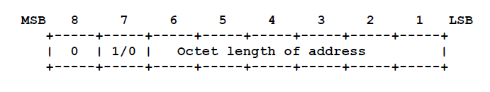
6.7.3 TL, ATM Number, and ATM Subaddress Encoding
 Where:
ATM addresses, as defined by the ATM Forum UNI 3.1 signaling specification [9], include a “Calling Party Number Information Element” and a “Calling Party Subaddress Information Element”. These Information Elements (IEs) SHOULD map to ATMARP/InATMARP source ATM number and source ATM subaddress respectively. Furthermore, ATM Forum defines a “Called Party Number Information Element” and a “Called Party Subaddress Information Element”. These IEs map to ATMARP/InATMARP target ATM number and target ATM subaddress, respectively.
The ATM Forum defines three structures for the combined use of number and subaddress [9]:
ATMARP and InATMARP requests and replies for ATM address structures 1 and 2 MUST indicate a null or unknown ATM subaddress by setting the appropriate subaddress length to zero; i.e., ar$sstl.length = 0 or ar$tstl.length = 0, the corresponding type field (ar$sstl.type or ar$tstl.type) MUST be ignored and the physical space for the ATM subaddress buffer MUST not be allocated in the ATMARP packet. For example, if ar$sstl.length=0, the storage for the source ATM subaddress is not allocated and the first byte of the source protocol address ar$spa follows immediately after the last byte of the source hardware address ar$sha in the packet.
Null or unknown ATM addresses MUST be indicated by setting the appropriate address length to zero; i.e., ar$shtl.length and ar$thtl.length is zero and the corresponding type field (ar$sstl.type or ar$tstl.type) MUST be ignored and the physical space for the ATM address or ATM subaddress buffer MUST not be allocated in the ATMARP packet.
6.7.4 ATMARP_NAK Packet Format
6.7.5 Variable Length Requirements for ATMARP Packets
ATMARP and InATMARP packets are variable in length. A null or unknown source or target protocol address is indicated by the corresponding length set to zero: e.g., when ar$spln or ar$tpln is zero the physical space for the corresponding address structure MUST not be allocated in the packet.
For backward compatibility with previous implementations, a null IPv4 protocol address may be received with length = 4 and an allocated address in storage set to the value 0.0.0.0. Receiving stations MUST be liberal in accepting this format of a null IPv4 address. However, on transmitting an ATMARP or InATMARP packet, a null IPv4 address MUST only be indicated by the length set to zero and MUST have no storage allocated.
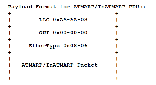
6.8 ATMARP/InATMARP Packet Encapsulation
The LLC value of 0xAA-AA-03 (3 octets) indicates the presence of a SNAP header.
The OUI value of 0x00-00-00 (3 octets) indicates that the following two-bytes is an EtherType.
The EtherType value of 0x08-06 (2 octets) indicates ARP [4].
The total size of the LLC/SNAP header is fixed at 8-octets. This aligns the start of the ATMARP packet on a 64-bit boundary relative to the start of the AAL5 CPCS-SDU.
The LLC/SNAP encapsulation for ATMARP/InATMARP presented here is consistent with the treatment of multiprotocol encapsulation of IP over ATM AAL5 as specified in [2] and in the format of ATMARP over IEEE 802 networks as specified in [5].
Traditionally, address resolution requests are broadcast to all directly connected IP members within a LIS. It is conceivable in the future that larger scaled ATM networks may handle ATMARP requests to destinations outside the originating LIS, perhaps even globally; issues raised by ATMARPing outside the LIS or by a global ATMARP mechanism are beyond the scope of this memo.
7. IP BROADCAST ADDRESS
ATM does not support broadcast addressing, therefore there are no mappings available from IP broadcast addresses to ATM broadcast services. Note: this lack of mapping does not restrict members from transmitting or receiving IP datagrams specifying any of the four standard IP broadcast address forms as described in [8]. Members, upon receiving an IP broadcast or IP subnet broadcast for their LIS, MUST process the packet as if addressed to that station.
This memo recognizes the future development of standards and implementations that will extend the operations as defined in this memo to provide an IP broadcast capability for use by the classical client.
8. IP MULTICAST ADDRESS
ATM does not directly support IP multicast address services, therefore there are no mappings available from IP multicast addresses to ATM multicast services. Current IP multicast implementations (i.e., MBONE and IP tunneling, see [10]) will continue to operate over ATM-based logical IP subnets if operated in the WAN configuration.
This memo recognizes the future development of ATM multicast service addressing by the ATM Forum. When available and widely implemented, the roll-over from the current IP multicast architecture to this new ATM architecture will be straightforward.
This memo recognizes the future development of standards and implementations that will extend the operations as defined in this memo to provide an IP multicast capability for use by the classical client.
9. SECURITY CONSIDERATIONS
Not all of the security issues relating to IP over ATM are clearly understood at this time, due to the fluid state of ATM specifications, the newness of the technology, and other factors.
It is believed that ATM and IP facilities for authenticated call management, authenticated end-to-end communications, and data encryption will be needed in globally connected ATM networks. Such future security facilities and their use by IP networks are beyond the scope of this memo.
There are known security issues relating to host impersonation via the address resolution protocols used on the Internet [13]. No special security mechanisms have been added to the address resolution mechanism defined here for use with networks using IP over ATM.
10. MIB SPECIFICATION
11. OPEN ISSUES
- Automatic configuration of client ATM addresses via DHCP [15] or via ATM UNI 3.1 Interim Local Management Interface (ILMI) services would be a useful extended service addition to this document and should be addressed in a separate memo.
- ATMARP packets are not authenticated. This is a potentially serious flaw in the overall system by allowing a mechanism by which corrupt information may be introduced into the server system.
12. REFERENCES
 |  |  |  |  |  |
