Error Detection and Correction
Posted on |
Error Detection and Correction
1 Introduction
Environmental interference and physical defects in the communication medium can cause random bit errors during data transmission. Error coding is a method of detecting and correcting these errors to ensure information is transferred intact from its source to its destination. Error coding is used for fault-tolerant computing in computer memory, magnetic and optical data storage media, satellite and deep space communications, network communications, cellular telephone networks, and almost any other form of digital data communication. Error coding uses mathematical formulas to encode data bits at the source into longer bit words for transmission. The “code word” can then be decoded at the destination to retrieve the information. The extra bits in the code word provide redundancy that, according to the coding scheme used, will allow the destination to use the decoding process to determine if the communication medium introduced errors and in some cases correct them so that the data need not be retransmitted. Different error coding schemes are chosen depending on the types of errors expected, the communication medium’s expected error rate, and whether or not data retransmission is possible. Faster processors and better communications technology make more complex coding schemes, with better error detecting and correcting capabilities, possible for smaller embedded systems, allowing for more robust communications. However, tradeoffs between bandwidth and coding overhead, coding complexity and allowable coding delay between transmissions, must be considered for each application.
Even if we know what type of errors can occur, we can’t simply recognize them. We can do this simply by comparing this copy received with another copy of intended transmission. In this mechanism, the source data block is sent twice. The receiver compares them with the help of a comparator and if those two blocks differ, a request for re-transmission is made. To achieve forward error correction, three sets of the same data block are sent and majority decision selects the correct block. These methods are very inefficient and increase the traffic two or three times. Fortunately, there are more efficient error detection and correction codes. There are two basic strategies for dealing with errors. One way is to include enough redundant information (extra bits are introduced into the data stream at the transmitter on a regular and logical basis) along with each block of data sent to enable the receiver to deduce what the transmitted character must have been. The other way is to include only enough redundancy to allow the receiver to deduce that error has occurred, but not which error has occurred and the receiver asks for a retransmission. The former strategy uses Error-Correcting Codes and latter uses Error-detecting Codes.
To understand how errors can be handled, it is necessary to look closely at what error really is. Normally, a frame consists of m-data bits (i.e., message bits) and r-redundant bits (or check bits). Let the total number of bits be n (m + r). An n-bit unit containing data and check-bits is often referred to as an n-bit code word.
Given any two code-words, say 10010101 and 11010100, it is possible to determine how many corresponding bits differ, just EXCLUSIVE OR the two code-words, and count the number of 1’s in the result. The number of bits position in which code words differ is called the Hamming distance. If two code words are a Hamming distance d-apart, it will require d single-bit errors to convert one code word to other. The error detecting and correcting properties depends on its Hamming distance.
- To detect d errors, you need a distance (d+1) code because with such a code there is no way that d-single bit errors can change a valid code word into another valid code word. Whenever receiver sees an invalid code word, it can tell that a transmission error has occurred.
- Similarly, to correct d errors, you need a distance 2d+1 code because that way the legal code words are so far apart that even with d changes, the original code word is still closer than any other code-word, so it can be uniquely determined.
2 Types of errors
These interferences can change the timing and shape of the signal. If the signal is carrying binary encoded data, such changes can alter the meaning of the data. These errors can be divided into two types: Single-bit error and Burst error.
Single-bit Error
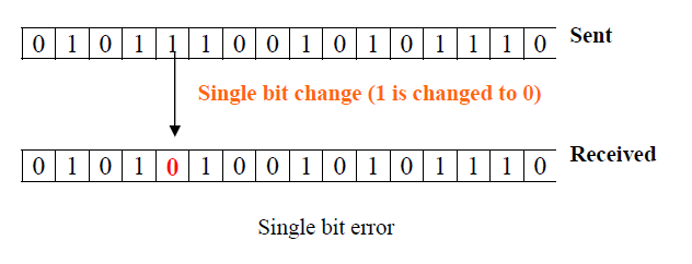
The term single-bit error means that only one bit of given data unit (such as a byte, character, or data unit) is changed from 1 to 0 or from 0 to 1 as shown in Fig.
Single bit errors are a least likely type of errors in serial data transmission. To see why to imagine a sender sends data at 10 Mbps. This means that each bit lasts only for 0.1 μs (micro-second). For a single bit error to occur noise must have a duration of only 0.1 μs (micro-second), which is very rare. However, a single-bit error can happen if we are having a parallel data transmission. For example, if 16 wires are used to send all 16 bits of a word at the same time and one of the wires is noisy, one bit is corrupted in each word.
Burst Error
The term burst error means that two or more bits in the data unit have changed from 0 to 1 or vice-versa. Note that burst error doesn’t necessary means that error occurs in consecutive bits. The length of the burst error is measured from the first corrupted bit to the last corrupted bit. Some bits in between may not be corrupted.
Burst errors are most likely to happen in serial transmission. The duration of the noise is normally longer than the duration of a single bit, which means that the noise affects data; it affects a set of bits as shown in Fig. The number of bits affected depends on the data rate and duration of the noise.
3 Error Detecting Codes
The basic approach used for error detection is the use of redundancy, where additional bits are added to facilitate detection and correction of errors. Popular techniques are:
- Simple Parity check
- Two-dimensional Parity check
- Checksum
- Cyclic redundancy check
3.1 Simple Parity Checking or One-dimension Parity Check
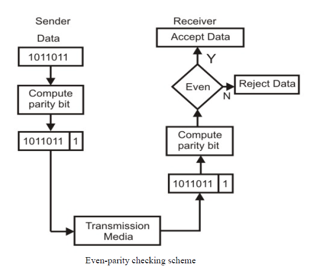
The most common and least expensive mechanism for error- detection is the simple parity check. In this technique, a redundant bit called parity bit is appended to every data unit so that the number of 1s in the unit (including the parity becomes even).
Blocks of data from the source are subjected to a check bit or Parity bit generator form, where a parity of 1 is added to the block if it contains an odd number of 1’s (ON bits) and 0 is added if it contains an even number of 1’s. At the receiving end, the parity bit is computed from the received data bits and compared with the received parity bit, as shown in Fig. 3.2.3. This scheme makes the total number of 1’s even, that is why it is called even parity checking. Considering a 4-bit word, different combinations of the data words and the corresponding code words are given in Table 3.1.
Table 3.1 Possible 4-bit data words and corresponding code words
Table 3.1
Note that for the sake of simplicity, we are discussing here the even-parity checking, where the number of 1’s should be an even number. It is also possible to use odd-parity checking, where the number of 1’s should be odd.
Performance
An observation of the table reveals that to move from one code word to another, at least two data bits should be changed. Hence these set of code words are said to have a minimum distance (hamming distance) of 2, which means that a receiver that has knowledge of the code word set can detect all single bit errors in each code word. However, if two errors occur in the code word, it becomes another valid member of the set and the decoder will see only another valid code word and know nothing of the error. Thus errors in more than one bit cannot be detected. In fact it can be shown that a single parity check code can detect the only odd number of errors in a code word.
3.2 Two-dimension Parity Check
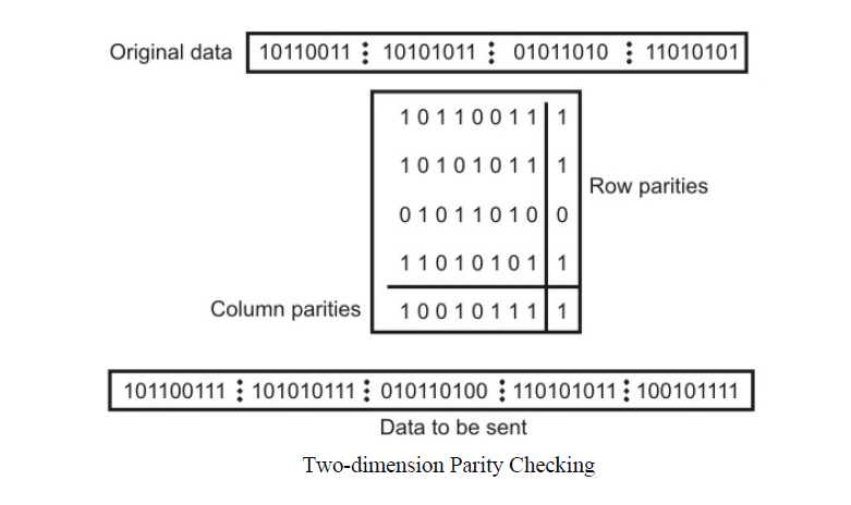
Performance can be improved by using two-dimensional parity check, which organizes the block of bits in the form of a table. Parity check bits are calculated for each row, which is equivalent to a simple parity check bit. Parity check bits are also calculated for all columns then both are sent along with the data. At the receiving end, these are compared with the parity bits calculated on the received data. This is illustrated in Fig.
Performance
Two- Dimension Parity Checking increases the likelihood of detecting burst errors. As we have shown in Fig. 3.2.4 that a 2-D Parity check of n bits can detect a burst error of n bits. A burst error of more than n bits is also detected by 2-D Parity check with a high probability. There is, however, one pattern of error that remains elusive. If two bits in one data unit are damaged and two bits in exactly same position in another data unit are also damaged, the 2-D Parity check checker will not detect an error. For example, if two data units: 11001100 and 10101100. If first and second from last bits in each of them is changed, making the data units as 01001110 and 00101110, the error cannot be detected by 2-D Parity check.
3.3 Checksum
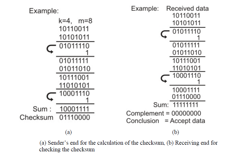
In checksum error detection scheme, the data is divided into k segments each of m bits. In the sender’s end the segments are added using 1’s complement arithmetic to get the sum. The sum is complemented to get the checksum. The checksum segment is sent along with the data segments as shown in Fig. (a). At the receiver’s end, all received segments are added using 1’s complement arithmetic to get the sum. The sum is complemented. If the result is zero, the received data is accepted; otherwise discarded, as shown in Fig. (b).
Performance
The checksum detects all errors involving an odd number of bits. It also detects most errors involving an even number of bits.
3.4 Cyclic Redundancy Checks (CRC)
This Cyclic Redundancy Check is the most powerful and easy to implement the technique. Unlike checksum scheme, which is based on addition, CRC is based on binary division. In CRC, a sequence of redundant bits, called cyclic redundancy check bits, are appended to the end of data unit so that the resulting data unit becomes exactly divisible by a second, predetermined binary number. At the destination, the incoming data unit is divided by the same number. If at this step there is no remainder, the data unit is assumed to be correct and is therefore accepted. A remainder indicates that the data unit has been damaged in transit and therefore must be rejected. The generalized technique can be explained as follows.
If a k bit message is to be transmitted, the transmitter generates an r-bit sequence, known as Frame Check Sequence (FCS) so that the (k+r) bits are actually being transmitted. Now this r-bit FCS is generated by dividing the original number, appended by r zeros, by a predetermined number. This number, which is (r+1) bit in length, can also be considered as the coefficients of a polynomial, called Generator Polynomial. The remainder of this division process generates the r-bit FCS. On receiving the packet, the receiver divides the (k+r) bit frame by the same predetermined number and if it produces no remainder, it can be assumed that no error has occurred during the transmission. Operations at both the sender and receiver end are shown in Fig.
This mathematical operation performed is illustrated in Fig. by dividing a sample 4-bit number by the coefficient of the generator polynomial x3+x+1, which is 1011, using the modulo-2 arithmetic. Modulo-2 arithmetic is a binary addition process without any carry over, which is just the Exclusive-OR operation. Consider the case where k=1101. Hence we have to divide 1101000 (i.e. k appended by 3 zeros) by 1011, which produces the remainder r=001 so that the bit frame (k+r) =1101001 is actually being transmitted through the communication channel. At the receiving end, if the received number, i.e., 1101001 is divided by the same generator polynomial 1011 to get the remainder as 000, it can be assumed that the data is free of errors.
The transmitter can generate the CRC by using a feedback shift register circuit. The same circuit can also be used at the receiving end to check whether any error has occurred. All the values can be expressed as polynomials of a dummy variable X. For example, for P = 11001 the corresponding polynomial is X4+X3+1. A polynomial is selected to have at least the following properties:
- It should not be divisible by X.
- It should not be divisible by (X+1).
The first condition guarantees that all burst errors of a length equal to the degree of polynomial are detected. The second condition guarantees that all burst errors affecting an odd number of bits are detected.
CRC process can be expressed as XnM(X)/P(X) = Q(X) + R(X) / P(X)
Commonly used divisor polynomials are:
CRC-16 = X16 + X15 + X2 + 1
CRC-CCITT = X16 + X12 + X5 + 1
CRC-32 = X32 + X26 + X23 + X22 + X16 + X12 + X11 + X10 + X8 + X7 + X5 + X4 + X2 + 1
Performance
CRC is a very effective error detection technique. If the divisor is chosen according to the previously mentioned rules, its performance can be summarized as follows:
- CRC can detect all single-bit errors
- CRC can detect all double-bit errors (three 1’s)
- CRC can detect any odd number of errors (X+1)
- CRC can detect all burst errors of less than the degree of the polynomial.
- CRC detects most of the larger burst errors with a high probability.
- For example, CRC-12 detects 99.97% of errors with a length 12 or more.
4 Error Correcting Codes
The techniques that we have discussed so far can detect errors, but do not correct them. Error Correction can be handled in two ways.
- One is when an error is discovered; the receiver can have the sender retransmit the entire data unit. This is known as backward error correction.
- In the other, the receiver can use an error-correcting code, which automatically corrects certain errors. This is known as forward error correction.
In theory, it is possible to correct any number of errors atomically. Error-correcting codes are more sophisticated than error detecting codes and require more redundant bits. The number of bits required correcting multiple-bit or burst error is so high that in most of the cases it is inefficient to do so. For this reason, most error correction is limited to one, two or at the most three-bit errors.
4.1 Single-bit error correction
The concept of error-correction can be easily understood by examining the simplest case of single-bit errors. As we have already seen that a single-bit error can be detected by addition of a parity bit (VRC) with the data, which needed to be send. A single additional bit can detect error, but it’s not sufficient enough to correct that error too. For correcting an error one has to know the exact position of er the or, i.e. exactly which bit is in error (to locate the invalid bits). For example, to correct a single-bit error in an ASCII character, the error correction must determine which one of the seven bits is in error. To this, we have to add some additional redundant bits.
To calculate the numbers of redundant bits (r) required to correct d data bits, let us find out the relationship between the two. So we have (d+r) as the total number of bits, which are to be transmitted; then r must be able to indicate at least d+r+1 different values. Of these, one value means no error, and remaining d+r values indicate error location of error in each of d+r locations. So, d+r+1 states must be distinguishable by r bits, and r bits can indicates 2r states. Hence, 2r must be greater than d+r+1.
2r >= d+r+1
The value of r must be determined by putting in the value of d in the relation. For example, if d is 7, then the smallest value of r that satisfies the above relation is 4. So the total bits, which are to be transmitted is 11 bits (d+r = 7+4 =11).
Now let us examine how we can manipulate these bits to discover which bit is in error. A technique developed by R.W.Hamming provides a practical solution. The solution or coding scheme he developed is commonly known as Hamming Code. Hamming code can be applied to data units of any length and uses the relationship between the data bits and redundant bits as discussed.
The basic approach for error detection by using Hamming code is as follows:
- To each group of m information bits k parity bits are added to form (m+k) bit code as shown in Fig. 3.2.8.
- Location of each of the (m+k) digits is assigned a decimal value.
- The k parity bits are placed in positions 1, 2, …, 2k-1 positions.–K parity checks are performed on selected digits of each codeword.
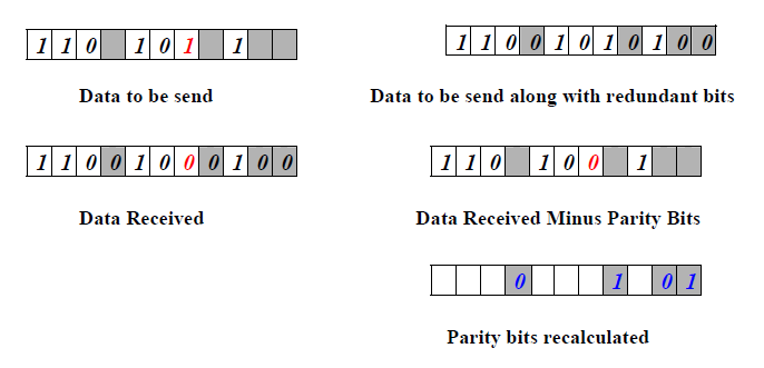
- At the receiving end, the parity bits are recalculated. The decimal value of the k parity bits provides the bit-position in error, if any.
The figure shows how hamming code is used for correction for 4-bit numbers (d4d3d2d1) with the help of three redundant bits (r3r2r1). For the example data 1010, first r1 (0) is calculated considering the parity of the bit positions, 1, 3, 5 and 7. Then the parity bits r2 is calculated considering bit positions 2, 3, 6 and 7. Finally, the parity bits r4 is calculated considering bit positions 4, 5, 6 and 7 as shown. If any corruption occurs in any of the transmitted code 1010010, the bit position in error can be found out by calculating r3r2r1 at the receiving end. For example, if the received code word is 1110010, the recalculated value of r3r2r1 is 110, which indicates that bit position in error is 6, the decimal value of 110.
Example:
Let us consider an example for 5-bit data. Here 4 parity bits are required. Assume that during transmission bit 5 has been changed from 1 to 0 as shown in Fig. 3.2.11. The receiver receives the code word and recalculates the four new parity bits using the same set of bits used by the sender plus the relevant parity (r) bit for each set (as shown in Fig. ). Then it assembles the new parity values into a binary number in order of r positions (r8, r4, r2, r1).
Calculations:
Parity recalculated (r8, r4, r2, r1) = 01012 = 510.
Hence, bit 5th is in error i.e. d5 is in error.
So, correct code-word which was transmitted is:
Books you may interested
 |  |  |  |  |  |

