
Frame Relay
Posted on |
Frame Relay
Introduction
Frame Relay is a high-performance WAN protocol that operates at the physical and data link layers of the OSI reference model. Frame Relay originally was designed for use across Integrated Services Digital Network (ISDN) interfaces. Today, it is used over a variety of other network interfaces as well.
Frame Relay is an example of a packet-switched technology. Packet-switched networks enable end stations to dynamically share the network medium and the available bandwidth. The following two techniques are used in packet-switching technology:
- Variable-length packets
- Statistical multiplexing
Variable-length packets are used for more efficient and flexible data transfers. These packets are switched between the various segments in the network until the destination is reached.
Statistical multiplexing techniques control network access in a packet-switched network. The advantage of this technique is that it accommodates more flexibility and more efficient use of bandwidth. Most of the today’s popular LANs, such as Ethernet and Token Ring, are packet-switched networks.
Frame Relay often is described as a streamlined version of X.25, offering fewer of the robust capabilities, such as windowing and retransmission of last data that are offered in X.25. This is because Frame Relay typically operates over WAN facilities that offer more reliable connection services and a higher degree of reliability. Frame Relay is strictly a Layer 2 protocol suite, whereas X.25 provides services at Layer 3 (the network layer) as well. This enables Frame Relay to offer higher performance and greater transmission efficiency than X.25 and makes Frame Relay suitable for current WAN applications, such as LAN interconnection.
Frame Relay Devices
Devices attached to a Frame Relay WAN fall into the following two general categories:
- Data terminal equipment (DTE)
- Data circuit-terminating equipment (DCE)
DTEs generally are considered to be terminating equipment for a specific network and typically are
located on the premises of a customer. Examples of DTE devices are terminals, personal computers, routers, and bridges.
DCEs are carrier-owned internetworking devices. The purpose of DCE equipment is to provide clocking and switching services in a network, which are the devices that actually transmit data through the WAN.
Frame Relay Virtual Circuits
Frame Relay provides connection-oriented data link layer communication. This means that a defined communication exists between each pair of devices and that these connections are associated with a connection identifier. This service is implemented by using a Frame Relay virtual circuit, which is a logical connection created between two data terminal equipment (DTE) devices across a Frame Relay packet-switched network (PSN).
Virtual circuits provide a bidirectional communication path from one DTE device to another and are uniquely identified by a data-link connection identifier (DLCI). A number of virtual circuits can be multiplexed into a single physical circuit for transmission across the network. This capability often can reduce the equipment and network complexity required to connect multiple DTE devices.
A virtual circuit can pass through any number of intermediate DCE devices (switches) located within the Frame Relay PSN.
Frame Relay virtual circuits fall into two categories: switched virtual circuits (SVCs) and permanent virtual circuits (PVCs).
Switched Virtual Circuits
Switched virtual circuits (SVCs) are temporary connections used in situations requiring only sporadic data transfer between DTE devices across the Frame Relay network. A communication session across an SVC consists of the following four operational states:
- Call setup — The virtual circuit between two Frame Relay DTE devices is established.
- Data transfer — Data is transmitted between the DTE devices over the virtual circuit.
- Idle — The connection between DTE devices is still active, but no data is transferred. If an SVC remains in an idle state for a defined period of time, the call can be terminated.
- Call termination — The virtual circuit between DTE devices is terminated.
After the virtual circuit is terminated, the DTE devices must establish a new SVC if there is additional data to be exchanged. It is expected that SVCs will be established, maintained, and terminated using the same signaling protocols used in ISDN.
Few manufacturers of Frame Relay DCE equipment support switched virtual circuit connections. Therefore, their actual deployment is minimal in today’s Frame Relay networks.
Permanent Virtual Circuits
Permanent virtual circuits (PVCs) are permanently established connections that are used for frequent and consistent data transfers between DTE devices across the Frame Relay network. Communication across a PVC does not require the call setup and termination states that are used with SVCs. PVCs always operate in one of the following two operational states:
- Data transfer — Data is transmitted between the DTE devices over the virtual circuit.
- Idle — The connection between DTE devices is active, but no data is transferred. Unlike SVCs, PVCs will not be terminated under any circumstances when in an idle state.
DTE devices can begin transferring data whenever they are ready because the circuit is permanently established.
Data-Link Connection Identifier
Frame Relay virtual circuits are identified by data-link connection identifiers (DLCIs). DLCI values typically are assigned by the Frame Relay service provider (for example, the telephone company).
Frame Relay DLCIs have local significance, which means that their values are unique in the LAN, but not necessarily in the Frame Relay WAN.

Congestion-Control Mechanisms
Frame Relay reduces network overhead by implementing simple congestion-notification mechanisms rather than explicit, per-virtual-circuit flow control. Frame Relay typically is implemented on reliable network media, so data integrity is not sacrificed because flow control can be left to higher-layer protocols. Frame Relay implements two congestion-notification mechanisms:
- Forward-explicit congestion notification (FECN)
- Backward-explicit congestion notification (BECN)
FECN and BECN each are controlled by a single bit contained in the Frame Relay frame header. The Frame Relay frame header also contains a Discard Eligibility (DE) bit, which is used to identify less important traffic that can be dropped during periods of congestion.
The FECN bit is part of the Address field in the Frame Relay frame header. The FECN mechanism is initiated when a DTE device sends Frame Relay frames into the network. If the network is congested, DCE devices (switches) set the value of the frames’ FECN bit to 1. When the frames reach the destination DTE device, the Address field (with the FECN bit set) indicates that the frame experienced congestion in the path from source to destination. The DTE device can relay this information to a higher-layer protocol for processing. Depending on the implementation, flow control may be initiated, or the indication may be ignored.
The BECN bit is part of the Address field in the Frame Relay frame header. DCE devices set the value of the BECN bit to 1 in frames traveling in the opposite direction of frames with their FECN bit set. This informs the receiving DTE device that a particular path through the network is congested. The DTE device then can relay this information to a higher-layer protocol for processing. Depending on the implementation, flow-control may be initiated, or the indication may be ignored.
The Discard Eligibility (DE) bit is used to indicate that a frame has lower importance than other frames. The DE bit is part of the Address field in the Frame Relay frame header.
DTE devices can set the value of the DE bit of a frame to 1 to indicate that the frame has lower importance than other frames. When the network becomes congested, DCE devices will discard frames with the DE bit set before discarding those that do not. This reduces the likelihood of critical data being dropped by Frame Relay DCE devices during periods of congestion.
Frame Relay uses a common error-checking mechanism known as the cyclic redundancy check (CRC). The CRC compares two calculated values to determine whether errors occurred during the transmission from source to destination. Frame Relay reduces network overhead by implementing error checking rather than error correction. Frame Relay typically is implemented on reliable network media, so data integrity is not sacrificed because error correction can be left to higher-layer protocols running on top of Frame Relay.
Frame Relay Local Management Interface
The Local Management Interface (LMI) is a set of enhancements to the basic Frame Relay specification. The LMI was developed in 1990 by Cisco Systems, StrataCom, Northern Telecom, and Digital Equipment Corporation. It offers a number of features (called extensions) for managing complex internetworks. Key Frame Relay LMI extensions include global addressing, virtual circuit status messages, and multicasting.
The LMI global addressing extension gives Frame Relay data-link connection identifier (DLCI) values globally rather than local significance. DLCI values become DTE addresses that are unique in the Frame Relay WAN. The global addressing extension adds functionality and manageability to Frame Relay internetworks. Individual network interfaces and the end nodes attached to them, for example, can be identified by using standard address-resolution and discovery techniques. In addition, the entire Frame Relay network appears to be a typical LAN to routers on its periphery.
LMI virtual circuit status messages provide communication and synchronization between Frame Relay DTE and DCE devices. These messages are used to periodically report on the status of PVCs, which prevents data from being sent into black holes (that is, over PVCs that no longer exist).
The LMI multicasting extension allows multicast groups to be assigned. Multicasting saves bandwidth by allowing routing updates and address-resolution messages to be sent only to specific groups of routers. The extension also transmits reports on the status of multicast groups in update messages.
Frame Relay Network Implementation
A common private Frame Relay network implementation is to equip a T1 multiplexer with both Frame Relay and non-Frame Relay interfaces. Frame Relay traffic is forwarded out the Frame Relay interface and onto the data network. Non-Frame Relay traffic is forwarded to the appropriate application or service, such as a private branch exchange (PBX) for telephone service or to a video-teleconferencing application.
A typical Frame Relay network consists of a number of DTE devices, such as routers, connected to remote ports on multiplexer equipment via traditional point-to-point services such as T1, fractional T1, or 56-Kb circuits. An example of a simple Frame Relay network is shown in Figure

The majority of Frame Relay networks deployed today are provisioned by service providers that intend to offer transmission services to customers. This is often referred to as a public Frame Relay service. Frame Relay is implemented in both public carrier-provided networks and in private enterprise networks.
Frame Relay Frame Formats
Flags indicate the beginning and end of the frame. Three primary components make up the Frame Relay frame: the header and address area, the user-data portion, and the frame check sequence (FCS). The address area, which is 2 bytes in length, is comprised of 10 bits representing the actual circuit identifier and 6 bits of fields related to congestion management. This identifier commonly is referred to as the data-link connection identifier (DLCI). Each of these is discussed in the descriptions that follow.
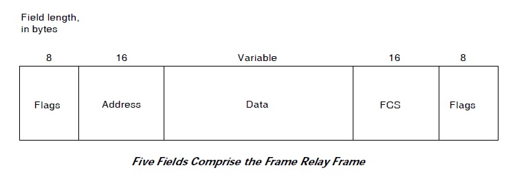
- Flags—Delimits the beginning and end of the frame. The value of this field is always the same and is represented either as the hexadecimal number 7E or as the binary number 01111110.
- Address—Contains the following information:
- Data — Contains encapsulated upper-layer data. Each frame in this variable-length field includes a user data or payload field that will vary in length up to 16,000 octets. This field serves to transport the higher-layer protocol packet (PDU) through a Frame Relay network.
- Frame Check Sequence — Ensures the integrity of transmitted data. This value is computed by the source device and verified by the receiver to ensure the integrity of transmission.
LMI Frame Format

- Flag—Delimits the beginning and end of the frame.
- LMI DLCI — Identifies the frame as an LMI frame instead of a basic Frame Relay frame. The LMI-specific DLCI value defined in the LMI consortium specification is DLCI = 1023.
- Unnumbered Information Indicator — Sets the poll/final bit to zero.
- Protocol Discriminator — Always contains a value indicating that the frame is an LMI frame.
- Call Reference — Always contains zeros. This field currently is not used for any purpose.
- Message Type — Labels the frame as one of the following message types:
- Information Elements — Contains a variable number of individual information elements (IEs). IEs consist of the following fields:
- Frame Check Sequence (FCS)—Ensures the integrity of transmitted data.
Books you may interested
 |  |  | ") |  |  |
