Multiprotocol Interconnect on X.25 and ISDN in the Packet Mode
Posted on |
Multiprotocol Interconnect on X.25 and ISDN in the Packet Mode
This document specifies the encapsulation of IP and other network layer protocols over X.25 networks, in accordance and alignment with ISO/IEC and CCITT standards. It is a replacement for RFC 877, “A Standard for the Transmission of IP Datagrams Over Public Data Networks” [1].
It was written to correct several ambiguities in the Internet Standard for IP/X.25 (RFC 877), to align it with ISO/IEC standards that have been written following RFC 877, to allow interoperable multiprotocol operation between routers and bridges over X.25, and to add some additional remarks based upon practical experience with the specification over the 8 years since that RFC.
The substantive change to the IP encapsulation is an increase in the allowed IP datagram Maximum Transmission Unit from 576 to 1600, to reflect existing practice.
This document also specifies the Internet encapsulation for protocols, including IP, on the packet mode of the ISDN. It applies to the use of Internet protocols on the ISDN in the circuit mode only when the circuit is established as an end-to-end X.25 connection.
2. Introduction
RFC 877 was written to document the method CSNET and the VAN Gateway had adopted to transmit IP datagrams over X.25 networks. Its success is evident in its current wide use and the inclusion of its IP protocol identifier in ISO/IEC TR 9577, “Protocol Identification in the Network Layer” [2], which is administered by ISO/IEC and CCITT.
However, due to changes in the scope of X.25 and the protocols that it can carry, several inadequacies have become evident in the RFC, especially in the areas of IP datagram Maximum Transmission Unit (MTU) size, X.25 maximum data packet size, virtual circuit management, and the interoperable encapsulation, over X.25, of protocols other than IP between multiprotocol routers and bridges.
As with RFC 877, one or more X.25 virtual circuits are opened on demand when datagrams arrive at the network interface for transmission. A virtual circuit is closed after some period of inactivity (the length of the period depends on the cost associated with an open virtual circuit). A virtual circuit may also be closed if the interface runs out of virtual circuits.
3. Standards
3.1
3.2
The first octet in the Call User Data (CUD) Field (the first data octet in the Call Request packet) is used for protocol demultiplexing, in accordance with the Subsequent Protocol Identifier (SPI) in ISO/IEC TR 9577. This field contains a one-octet Network Layer Protocol Identifier (NLPID), which identifies the network layer protocol encapsulated over the X.25 virtual circuit. The CUD field MAY contain more than one octet of information, and receivers MUST ignore all extraneous octets in the field.
In the following discussion, the most significant digit of the binary numbers is left-most. For the Internet community, the NLPID has four relevant values:
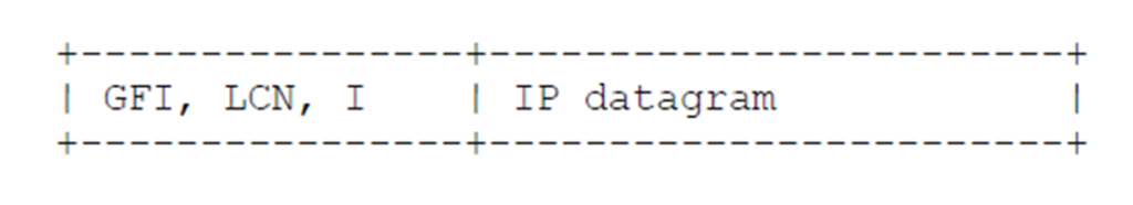
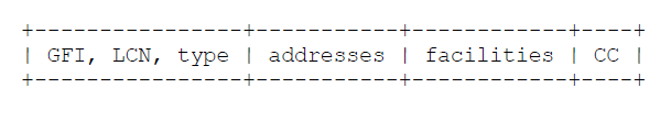
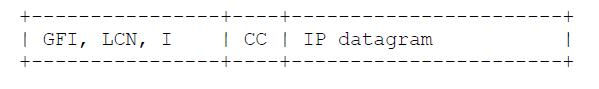
The value hex CC (binary 11001100, decimal 204) is IP [6]. Conformance with this specification requires that IP be supported. See section 5.1 for a diagram of the packet formats.
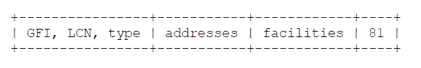
The value hex 81 (binary 10000001, decimal 129) identifies ISO/IEC 8473 (CLNP) [4]. ISO/IEC TR 9577 specifically allows other ISO/IEC connectionless-protocol packets, such as ES-IS and IS-IS, to also be carried on the same virtual circuit as CLNP. Conformance with this specification does not require that CLNP be supported. See section 5.2 for a diagram of the packet formats.
The value hex 82 (binary 10000010, decimal 130) is used specifically for ISO/IEC 9542 (ES-IS) [5]. If there is already a circuit open to carry CLNP, then it is not necessary to open the second circuit to carry ES-IS. Conformance with this specification does not require that ES-IS be supported.
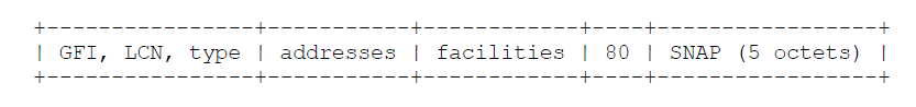
The value hex 80 (binary 10000000, decimal 128) identifies the use of IEEE Subnetwork Access Protocol (SNAP) [3] to further encapsulate and identify a single network-layer protocol. The SNAP-encapsulated protocol is identified by including a five-octet SNAP header in the Call Request CUD field immediately following the hex 80 octet. SNAP headers are not included in the subsequent X.25 data packets. Only one SNAP-encapsulated protocol may be carried over a virtual circuit opened using this encoding. The receiver SHOULD accept the incoming call only if it can support the particular SNAP-identified protocol.
Conformance with this specification does not require that this SNAP encoding be supported. See section 5.3 for a diagram of the packet formats.
The value hex 00 (binary 00000000, decimal 0) identifies the Null encapsulation, used to multiplex multiple network layer protocols over the same circuit. This encoding is further discussed in section 3.3 below.
The “Assigned Numbers” RFC [7] contains one other non-CCITT and non-ISO/IEC value that has been in active use for Internet X.25 encapsulation identification, namely hex C5 (binary 11000101, decimal 197) for Blacker X.25. This value MAY continue to be used, but only by prior pre-configuration of the sending and receiving X.25 interfaces to support this value. The value hex CD (binary 11001101, decimal 205), listed in “Assigned Numbers” for “ISO-IP”, is also used by Blacker and also can only be used by prior pre-configuration of the sending and receiving X.25 interfaces.
Each system MUST only accept calls for protocols it can process; every Internet system MUST be able to accept the CC encapsulation for IP datagrams. A system MUST NOT accept calls, and then immediately clear them. Accepting the call indicates to the calling system that the protocol encapsulation is supported; on some networks, a call accepted and cleared is charged, while a call cleared in the request state is not charged.
Systems that support NLPIDs other than hex CC (for IP) SHOULD allow their use to be configured on a per-peer address basis. The use of hex CC (for IP) MUST always be allowed between peers and cannot be configured.
3.3
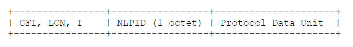
The NLPID encodings discussed in section 3.2 only allow a single network layer protocol to be sent over a circuit. The Null encapsulation, identified by a NLPID encoding of hex 00, is used in order to multiplex multiple network layer protocols over one circuit.
When the Null encapsulation is used, each X.25 complete packet sequence sent on the circuit begins with a one-octet NLPID, which identifies the network layer protocol data unit contained only in that particular complete packet sequence. Further, if the SNAP NLPID (hex 80) is used, then the NLPID octet is immediately followed by the five-octet SNAP header, which is then immediately followed by the encapsulated PDU. The encapsulated network layer protocol MAY differ from one complete packet sequence to the next over the same circuit.
When a receiver is presented with an Incoming Call identifying the Null encapsulation, the receiver MUST accept the call if it supports the Null encapsulation for any network layer protocol. The receiver MAY then silently discard a multiplexed PDU if it cannot support that particular encapsulated protocol. See section 5.4 for a diagram of the packet formats.
Use of the single network layer protocol circuits described in section 3.2 is more efficient in terms of bandwidth if only a limited number of protocols are supported by a system. It also allows each system to determine exactly which protocols are supported by its communicating partner. Other advantages include being able to use X.25 accounting to detail each protocol and different quality of service or flow control windows for different protocols.
The Null encapsulation, for multiplexing, is useful when a system, for any reason (such as implementation restrictions or network cost considerations), may only open a limited number of virtual circuits simultaneously. This is the method most likely to be used by a multiprotocol router, to avoid using an unreasonable number of virtual circuits.
If performing IEEE 802.1d bridging across X.25 is desired, then the Null encapsulation MUST be used. See section 4.2 for a further discussion.
Conformance with this specification does not require that the Null encapsulation be supported.
Systems that support the Null encapsulation SHOULD allow its use to be configured on a per-peer address basis.
3.4
For compatibility with existing practice, and RFC 877 systems, IP datagrams MUST, by default, be encapsulated on a virtual circuit opened with the CC CUD.
- IP may be contained in multiplexed data packets on a circuit using the Null (multiplexed) encapsulation. Such data packets are identified by a NLPID of hex CC.
- IP may be encapsulated within the SNAP encapsulation on a circuit. This encapsulation is identified by containing, in the 5-octet SNAP header, an Organizationally Unique Identifier (OUI) of hex 00-00-00 and Protocol Identifier (PID) of hex 08-00.
- On a circuit using the Null encapsulation, IP may be contained within the SNAP encapsulation of IP in multiplexed data packets.
3.5
The negotiable facilities of X.25 MAY be used (e.g., packet and window size negotiation). Since PDUs are sent as complete packet sequences, any maximum X.25 data packet size MAY be configured or negotiated between systems and their network service providers. See section 4.5 for a discussion of maximum X.25 data packet size and network performance.
There is no implied relationship between PDU size and X.25 packet size (i.e., the method of setting IP MTU based on X.25 packet size in RFC 877 is not used).
3.6
Every system MUST be able to receive and transmit PDUs up to at least 1600 octets in length.
For compatibility with existing practice, as well as interoperability with RFC 877 systems, the default transmits MTU for IP datagrams SHOULD default to 1500, and MUST be configurable in at least the range 576 to 1600.
This is done with a view toward a standard default IP MTU of 1500, used on both local and wide area networks with no fragmentation at routers. Actually redefining the IP default MTU is, of course, outside the scope of this specification.
The PDU size (e.g., IP MTU) MUST be configurable, on at least a per-interface basis. The maximum transmitted PDU length SHOULD be configurable on a per-peer basis and MAY be configurable on a per-encapsulation basis as well. Note that the ability to configure to send IP datagrams with an MTU of 576 octets and to receive IP datagrams of 1600 octets is essential to interoperate with existing implementations of RFC 877 and implementations of this specification.
Note that on circuits using the Null (multiplexed) encapsulation, when IP packets are encapsulated using the NLPID of hex CC, then the default IP MTU of 1500 implies a PDU size of 1501; a PDU size of 1600 implies an IP MTU of 1599. When IP packets are encapsulated using the NLPID of hex 80 followed by the SNAP header for IP, then the default IP MTU of 1500 implies a PDU size of 1506; a PDU size of 1600 implies an IP MTU of 1594.
Of course, an implementation MAY support a maximum PDU size larger than 1600 octets. In particular, there is no limit to the size that may be used when explicitly configured by communicating peers.
3.7
Each ISO/IEC TR 9577 encapsulation (e.g., IP, CLNP, and SNAP) requires a separate virtual circuit between systems. In addition, multiple virtual circuits for a single encapsulation MAY be used between systems, to, for example, increase throughput (see notes in section 4.5).
Receivers SHOULD accept multiple incoming calls with the same encapsulation from a single system. Having done so, receivers MUST then accept incoming PDUs on the additional circuit(s), and SHOULD transmit on the additional circuits.
Shedding load by refusing additional calls for the same encapsulation with a X.25 diagnostic of 0 (DTE clearing) is correct practice, as is shortening inactivity timers to try to clear circuits.
Receivers MUST NOT accept the incoming call, only to close the circuit or ignore PDUs from the circuit.
Because opening multiple virtual circuits specifying the same encapsulation is specifically allowed, algorithms to prevent virtual circuit call collision, such as the one found in section 8.4.3.5 of ISO/IEC 8473 [4], MUST NOT be implemented.
While allowing multiple virtual circuits for a single protocol is specifically desired and allowed, implementations MAY choose (by configuration) to permit only a single circuit for some protocols to some destinations. Only in such a case, if a colliding incoming call is received while a call request is pending, the incoming call shall be rejected. Note that this may result in a failure to establish a connection. In such a case, each system shall wait at least a configurable collision retry time before retrying. Adding a random increment, with exponential backoff if necessary, is recommended.
3.8
3.9
Each system MUST use an inactivity timer to clear virtual circuits that are idle for some period of time. Some X.25 networks, including the ISDN under present tariffs in most areas, charge for virtual circuit holding time. Even where they do not, the resource SHOULD be released when idle. The timer SHOULD be configurable; a timer value of “infinite” is acceptable when explicitly configured.
The default SHOULD be a small number of minutes. For IP, a reasonable default is 90 seconds.
3.10
Systems SHOULD allow calls from unconfigured calling addresses (presumably not collect calls, however); this SHOULD be a configuration option. A system accepting such a call will, of course, not transmit on that virtual circuit if it cannot determine the protocol (e.g., IP) address of the caller. As an example, on the DDN this is not a restriction because IP addresses can be determined algorithmically based upon the caller’s X.121 address [7,9].
Allowing such calls helps work around various “helpful” address translations done by the network(s), as well as allowing experimentation with various address resolution protocols.
3.11
3.12
3.13
The following X.25 features MUST NOT be used: interrupt packets and the Q bit (indicating qualified data). Other X.25 features not explicitly discussed in this document, such as fast select and the D bit (indicating end-to-end significance) SHOULD NOT be used.
Use of the D bit will interfere with the use of the M bit (more data sequences) required for identification of PDUs. In particular, a subscription to the D bit modification facility (X.25-1988, section 3.3) will prevent proper operation, this user facility MUST NOT be subscribed.
3.14
4. General Remarks
4.1
4.2
4.3
4.4
It is often assumed that a larger X.25 data packet size will result in increased performance. This is not necessarily true: in typical X.25 networks, it will actually decrease performance.
Many, if not most, X.25 networks completely store X.25 data packets in each switch before forwarding them. If the X.25 network requires a path through a number of switches, and low-speed trunks are used, then negotiating and using large X.25 data packets could result in large transit delays through the X.25 network as a result of the time required to clock the data packets over each low-speed trunk.
If a small end-to-end window size is also used, this may also adversely affect the end-to-end throughput of the X.25 circuit. For this reason, segmenting large IP datagrams in the X.25 layer into complete packet sequences of smaller X.25 data packets allows a greater amount of pipelining through the X.25 switches, with subsequent improvements in end-to-end throughput.
Large X.25 data packet size combined with slow (e.g., 9.6Kbps) physical circuits will also increase individual packet latency for other virtual circuits on the same path; this may cause unacceptable effects on, for example, X.29 connections.
This discussion is further complicated by the fact that X.25 networks are free to internally combine or split X.25 data packets as long as the complete packet sequence is preserved.
The optimum X.25 data packet size is, therefore, dependent on the network, and is not necessarily the largest size offered by that network.
4.5
Another method of increasing performance is to open multiple virtual circuits to the same destination, specifying the same CUD. Like packet size, this is not always the best method.
When the throughput limitation is due to X.25 window size, opening multiple circuits effectively multiplies the window, and may increase performance.
However, opening multiple circuits also competes more effectively for the physical path, by taking more shares of the available bandwidth. While this may be desirable to the user of the encapsulation, it may be somewhat less desirable to the other users of the path.
Opening multiple circuits may also cause datagram sequencing and reordering problems in end systems with limited buffering (e.g., at the TCP level, receiving segments out of order, when a single circuit would have delivered them in order). This will only affect performance, not correctness of operation.
Opening multiple circuits may also increase the cost of delivering datagrams across a public data network.
4.6
This document does not specify any method of dynamic IP to X.25 (or X.121) address resolution. The problem is left for further study.
Typical present-day implementations use static tables of varying kinds or an algorithmic transformation between IP and X.121 addresses [7,9]. There are proposals for other methods. In particular, RFC 1183 [10] describes Domain Name System (DNS) resource records that may be useful either for automatic resolution or for maintenance of static tables. Use of these method(s) is entirely experimental at this time.
5. Packet Formats
5.1
 X.25 data packets:
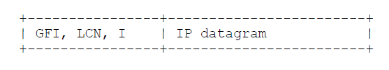
5.2
 X.25 data packets:
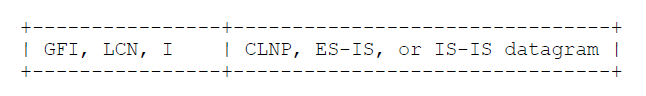 (Note that these datagrams are self-identifying in their first octet).
5.3
 X.25 data packets:
 5.4
5.4


 Multiplexed CLNP datagram:
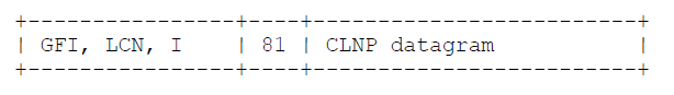 Multiplexed SNAP PDU:
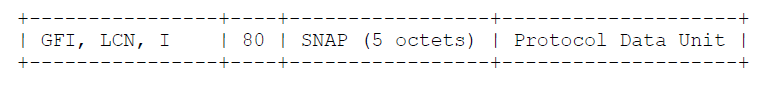
6. References
[5] ISO/IEC 9542, Information processing systems -Telecommunications and information exchange between systems -End system to intermediate system routeing protocol for use in conjunction with the protocol for providing the connectionless-mode network service (ISO/IEC 8473), 1988.
[6] Postel, J., Editor., “Internet Protocol – DARPA Internet Program Protocol Specification”, RFC 791, USC/Information Sciences Institute, September 1981.
[7] Reynolds, J. and J. Postel, “Assigned Numbers”, RFC 1340, USC/Information Sciences Institute, July 1992.
[8] Bradley, T., Brown, C., and A. Malis, “Multiprotocol Interconnect over Frame Relay”, RFC 1294, Wellfleet Communications and BBN Communications, January 1992.
[9] “Defense Data Network X.25 Host Interface Specification”, contained in “DDN Protocol Handbook”, Volume 1, DDN Network Information Center 50004, December 1985.
[10] Everhart, C., Mamakos, L., Ullmann, R, and P. Mockapetris, Editors, “New DNS RR Definitions”, RFC 1183, Transarc, University of Maryland, Prime Computer, USC/Information Sciences Institute, October 1990.
[11] ISO/IEC 8208, Information processing systems – Data
 |  |  |  |  |  |
 |  |  |  |  |  |
