VSAT Site Survey
Posted on |
VSAT Site Survey
The purpose of the site survey is
- To identify site accessibility
- To select equipment locations prior to installation
- To identify available mounting surfaces
- To identify obstructions
- To plan cable routing
- To identify RF earth grounding
- To identify the availability of AC power and grounding
- To identify RF/IF interference sources
Search VSAT Satellite Receiver Suppliers
Site Accessibility
The VSAT racks and antenna equipment are delivered in crates or boxes and some sites may require antenna equipment to be lifted to the roof by crane. The delivery and installation site should be surveyed to determine whether the delivery vehicle, forklifts, and crane have sufficient access and solid ground during the period of planned installation. In other words, if the site survey is conducted in summer consider whether conditions will remain favorable several months later when the actual installation will take place. Take several pictures of the access and installation area to help recall details of installation after the site survey is complete.
Equipment Locations
First, determine the antenna mounting surface, whether it is on a building or the ground, based on building codes, desired indoor unit location, available mounting surfaces, cable length restrictions, available AC power, available Earth grounding, and available workspace. Don’t forget that many cities require permits to erect antenna for installation workspace. Take pictures of the proposed antenna and network terminal installation site.
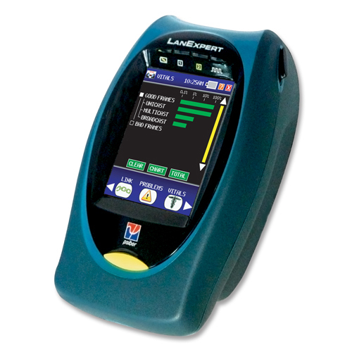
Psiber LE85M/S, LanExpert 85M/S Cable and Network Analyzer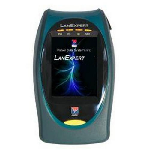
Available Mounting Surfaces
If the antenna installation will be on the ground, consider the composition of the surface material (asphalt, concrete, soil, etc.) Plan for any special surface modifications which might need to take place (i.e. installation of the concrete slab, etc.)
Also, consider the whether or not this is a pedestrian or vehicle traffic area. If it is, some additional safety equipment (fences, radiation warnings, etc.) may need to be installed. Special cable routing may also be required.
If antenna installation will be on the building, consider whether it will be wall or roof mount. For a wall mount, check support structure type (brick, concrete, wood, etc.). For a roof mount, also check the support structure type (tar, gravel, metal, concrete, shingle, etc.) and superstructure support type (wood, steel, etc.)
Whether the surface type, take pictures of the outside and inside (if possible) mounting surface.
Identifying Obstructions
Obstructions not identified prior to the installation can cause big delays. Remember to note power lines, antenna towers, sharp or narrow corners, etc. for crane /truck access.
Also check under the mounting surface for irrigation pipes, power conduits, air conditioning and heating ducts, etc. which will either need to be rerouted or otherwise avoided.
Be sure that there is enough room for antenna reflector movement. Remember that the current satellite will not remain in orbit forever and that the antenna may need to be aligned to a satellite at different azimuth and elevation. Watch out for walls, air conditioning units, fences, etc. which could limit the antenna movement. Antenna movement over ±450 range from original center azimuth is normally sufficient.
Don’t forget to take a look at expected radiation path from the antenna to satellite. Look for buildings, trees (present and future), hills mountains, etc. that may partially or fully shade the satellite signal.
Take picture of the satellite signal path and a complete 3600 circle around the antenna location. These pictures will be used to help identify obstructions and potential RF interference sources.
Cable Routing
Often, cable routing and length are the most limiting installation considerations. The point of structural entry from the antenna to the network terminals the first consideration. Keep in mind that there is a minimum bend radius for the coaxial cables which will be installed. Allow a minimum bend radius of no less than four inches (10mm). Don’t forget about sealing the entry point after installation.
Preplan the exact cable route and length, and then add about 10 or 15% to provide a margin of safety. Take a time to draw the cable route on scale building drawings. Don’t forget to include the rise and fall distances of up and down walls, racks, and the antenna structure. Avoid running the cables in the existing conduit with AC and other communications cables. This reduces the possibility of interference between equipment. Also, avoid running the cable next to moving objects like elevators. Where cable must cross, try to cross at right angles to eliminate induced signals.
Where possible, use metal, grounded conduit cable routing. Properly grounded metal conduit provides additional radio frequency and noise interference protection to the desired signals and protects the cable from future damage by individuals making changes to the building (i.e. drilling or cutting holes in walls where cables are installed). Additional cable protection may be required if the cable is going to be buried or suspended over a long distance, to protect it from being cut and prevent strain on the connectors.
The cables should be secured in place, particularly near the radio and network terminal equipment. Remember that gravity may cause the center conductor to slip down inside the coaxial cable over long vertical runs. The best method of reducing this is the use of the shortest available vertical installation, coupled with frequent tie-down points.
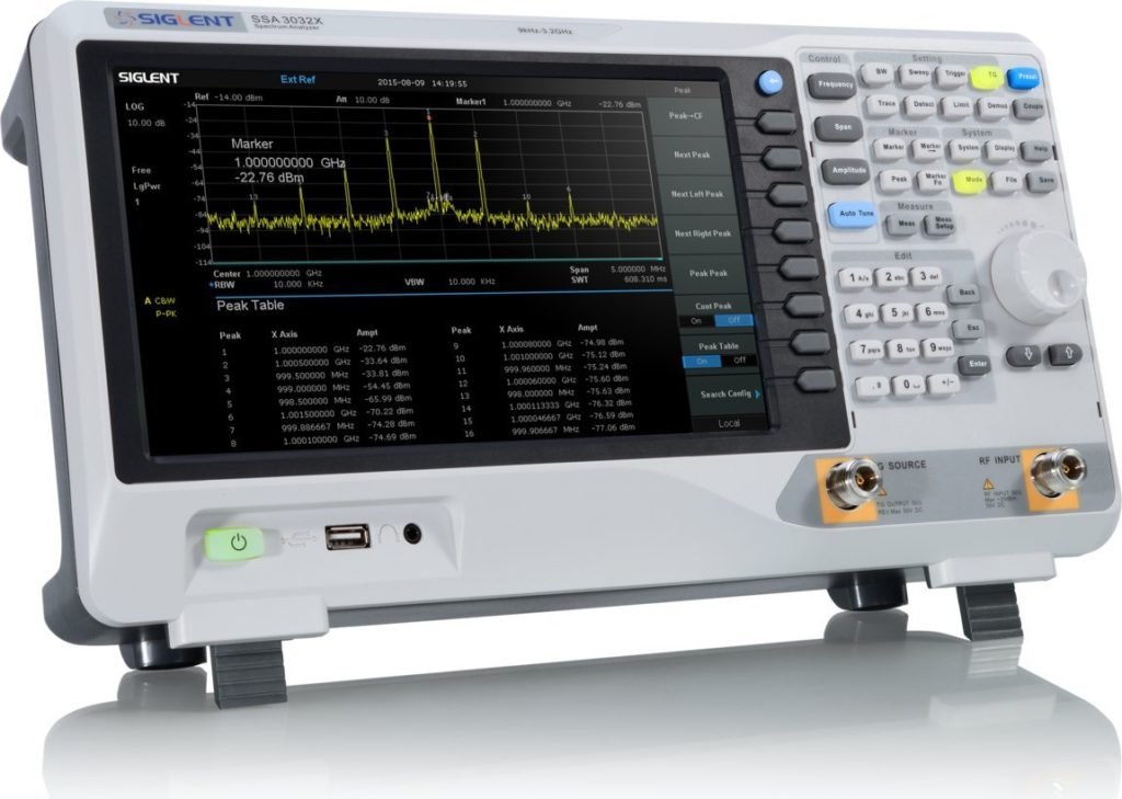
1GHZ DSX CABLE ANALYZER V2 W/WIFI
RF Earth Grounding
Earth grounding is the most significant resource available to reducing performance between the equipment and it makes up half of the receive and transmits signal in the RF system. Unfortunately, it is often the most overlooked aspects of an installation. Most people don’t even know they have a grounding problem until them to add a new piece of equipment, and suddenly most or all of their equipment fails when new equipment is turned on. Normally new equipment is blamed for the failures, regardless of whether the new equipment is properly engineered and produced. Some companies think they have a good ground system in place. Take the time to do a ground survey (of a sort) prior to the installation. It is important to remember that there are several different types of grounds.
First, identify the available Earth ground points already available at an installation site. Find out what other equipment is being used on the premises. Lower frequency radios, Large AC motors (such as elevators, compressors and factory machinery), and high power equipment requires a large Earth ground surface area. The amount of Earth ground available is dependent upon the composition and connectivity of soil. Generally, soil which is moist and easily vegetated provides the best earth ground. The less moist and vegetative the soil, the worse the Earth ground is. With this in mind, a good Earth ground could simply consist of a copper rod driven several feet into the ground or require a grounding grid that is buried and covering a large surface area.
Take the time to see what other equipment is installed at the site, and ask what other equipment will be installed in the near future. Then identify the ground the ground cable type required based on the effectiveness of available Earth ground. It may necessary, in some cases, to have a professional ground survey done.
Be sure not to use floating grounds or grounds occupied by motor or generators. All high power, low-frequency equipment, motors, and generators should have their own dedicated Earth ground. Remember also, the more equipment connected to a single grounding system, the less effective the single grounding system becomes.
Take a picture of the grounding system.
Availability of Power
Most radio equipment has its own AC power supply, Verify that AC power is available to both the indoor and outdoor unit locations and that the circuit breaker panels are properly sized to handle the load.
RF/IF Interface Sources
Perform a terrestrial interface survey, particularly for C-Band installations. When performing the survey, don’t just take one quick sample at each bearing. Take samples over four or more hours of complete 3600 azimuths, to ensure that local terrestrial interface sources are properly identified and corrected. Possible sources of interference could be passing vehicles, airports, or military installations, building motors (elevators, etc.), generators air conditioning units, and multipath (reflected) signals.
Frequencies of concern:
- 52 to 88 MHz
- 950 to 1450 Mhz
- 3700 to 6425 Mhz
RF / IF Interference Solutions
Some solutions to the above problems:
- Use different cable routing if the noise source is along the IF cable route.
- Provide better Earth grounding both at the noise source and the antenna / VSAT.
- Construct an RF shielding between the noise source and the antenna or an RF shelter around the noise source.
- Relocate the antenna or VSAT
Taking the time to conduct a terrestrial interface survey is well worth and effort. There is nothing more discouraging than installation the antenna and network terminals correctly, and not being able to make a network connection due to interference caused outside of the network. Sometimes the operation will be intermittent, making a situation even more aggravating. This is why the terrestrial survey must be done over many hours.
Books you may interested
 |  |  |
