The Fundamentals of SONET
Posted on |
Overview
In 1985, Bellcore proposed the idea of an optical carrier-to-carrier interface that would allow the interconnection of different manufacturers’ optical equipment. This was based on a hierarchy of digital rates, all formed by the interleaving of a basic rate signal. The idea of a Synchronous Optical NETwork (SONET) attracted the interest of carriers.
When fibre optical cables were initially deployed as a medium for high-speed digital transport, the lack of standards led to the widespread deployment of proprietary optical interfaces. This meant that fibre optic transmission equipment from one manufacturer could not interface with equipment from any of the other manufacturers. Service providers were required to select a single vendor for deployment throughout the network and they were locked into the network control and monitoring capabilities of that manufacturer. Although this technology satisfied the bandwidth needs of the network for several years, it was evident that this arrangement could not support the future needs of the industry because of the limited interconnection capabilities.
As stated above in 1985, Bellcore proposed the idea of an optical carrier-to-carrier interface that would allow the interconnection of different manufacturers’ optical equipment. This was based on a hierarchy of digital rates, all formed by the interleaving of a basic rate signal. The idea of a Synchronous Optical NETwork (SONET) attracted the interest of carriers, Regional Bell Operating Companies (RBOCs), and manufacturers alike and quickly gained momentum. Interest in SONET by CCITT (now International Telecommunication Union – ITU-T) expanded its scope from a domestic to an international standard, and by 1988 the ANSI committee had successfully integrated changes requested by the ITU-T and was well on their way toward the issuance of the new standard. Today, the SONET standard is contained in the ANSI specification T1.105 Digital Hierarchy – Optical Interface Rates & Formats Specifications (SONET), and technical recommendations are found in Bellcore TR-NWT-000253 Synchronous Optical Network (SONET) Transport Systems: Common Generic Criteria.The SONET specifications define optical carrier (OC) interfaces and their electrical equivalents to allow transmission of lower-rate signals at a common synchronous rate. One of the benefits of the SONET signal, as with any standard, is that it allows multiple vendors provide compatible transmission equipment in the same span. SONET also allows for a dynamic drop and insert capabilities on the payload without the delay and additional hardware associated with demultiplexing and remultiplexing the higher rate signal. Since the overhead is relatively independent of the payload, SONET is able to integrate new services, such as Asynchronous Transfer Mode (ATM) and Fiber Distributed Data Interface (FDDI), in addition to existing DS3 and DS1 services. Another major advantage of SONET is that the operations, administration, maintenance, and provisioning (OAM&P) capabilities are built directly into the signal overhead to allow maintenance of the network from one central location.
SONET Multiplexing
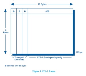
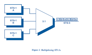
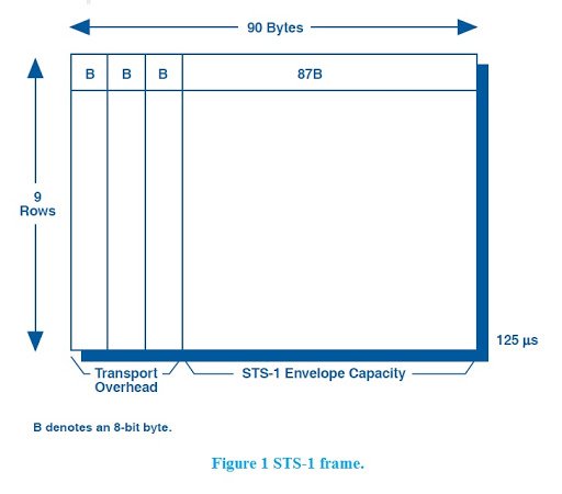
SONET multiplexing combines low-speed digital signals such as DS1, DS1C, E1, DS2, and DS3 with required overhead to form a building block called Synchronous Transport Signal Level One (STS-1).
SONET Frame
SONET Signal Hierarchy
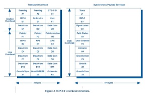
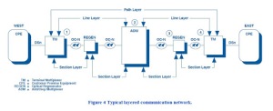
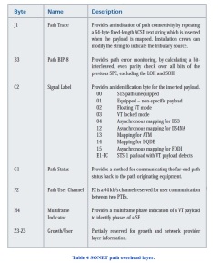
The SONET signal is layered to divide responsibility for transporting the payload through the network. Each network element (NE) is responsible for interpreting and generating its overhead layer, and for communicating control and status information to the same layer in other equipment – in short, “terminating” its overhead layer. As the payload travels through the SONET network, each layer is terminated by one of a general class of NEs, termed section terminating equipment (STE), line terminating equipment (LTE), or path terminating equipment (PTE). Figure 4 illustrates a sample network with the layered functions identified. The POH is generated at the point where the lower-rate signal enters the SONET network by PTE such as a terminal multiplexer (TM). The POH is removed when the payload exits the network. Since the POH is first-on last-off, alarm and error information contained within this layer represents end-to-end status.
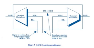
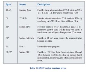
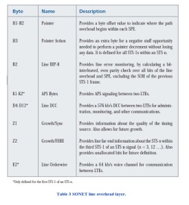
The next layer of overhead termination is the LOH and is performed by the LTE such as a SONET add/drop multiplexer (ADM). The LOH is where most of the communication and synchronization between Nes occurs, and represents error information between major nodes in the network. Finally, SOH is terminated by STE, such as optical regenerators, and contains error information between every node in the network. In many cases, LTE, PTE, and STE functions are combined with the identical piece of equipment. Since each layer is terminated and regenerated at the appropriate nodes, the performance monitoring data at each NE will help to sectionalize a problem.
For example, if traffic is traveling west to east in Figure 4,
SONET Section, Line, and Path Overhead Layers
 |  |  |  |  |  |
