
Transmission of IPv6 Packets over Ethernet Networks
Posted on |
 |  |  |
Transmission of IPv6 Packets over Ethernet Networks
1. Introduction
This document specifies the frame format for transmission of IPv6 packets and the method of forming IPv6 link-local addresses and statelessly autoconfigured addresses on Ethernet networks. It also specifies the content of the Source/Target Link-layer Address option used in Router Solicitation, Router Advertisement, Neighbor Solicitation, Neighbor Advertisement and Redirects messages when those messages are transmitted on an Ethernet.
2. Maximum Transmission Unit
The default MTU size for IPv6 [RFC 2460] packets on an Ethernet is 1500 octets. This size may be reduced by a Router Advertisement [RFC 2461] containing an MTU option which specifies a smaller MTU, or by manual configuration of each node. If a Router Advertisement received on an Ethernet interface has an MTU option specifying an MTU larger than 1500, or larger than a manually configured value, that MTU option may be logged to system management but must be otherwise ignored.
For purposes of this document, information received from DHCP is considered “manually configured” and the term Ethernet includes CSMA/CD and full-duplex subnetworks based on ISO/IEC 8802-3, with various data rates.
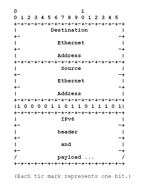
3. Frame Format

4. Stateless Autoconfiguration
The Interface Identifier [RFC 2373] for an Ethernet interface is based on the EUI-64 identifier [“Guidelines For 64-bit Global Identifier (EUI-64)”, http://standards.ieee.org/db/oui/tutorials/EUI64.html] derived from the interface’s built-in 48-bit IEEE 802 address. The EUI-64 is formed as follows. (Canonical bit order is assumed throughout.)
The OUI of the Ethernet address (the first three octets) becomes the company_id of the EUI-64 (the first three octets). The fourth and fifth octets of the EUI are set to the fixed value FFFE hexadecimal. The last three octets of the Ethernet address become the last three octets of the EUI-64.
The Interface Identifier is then formed from the EUI-64 by complementing the “Universal/Local” (U/L) bit, which is the next-to-lowest order bit of the first octet of the EUI-64. Complementing this bit will generally change a 0 value to a 1, since an interface’s built-in address is expected to be from a universally administered address space and hence have a globally unique value. A universally administered IEEE 802 address or an EUI-64 is signified by a 0 in the U/L bit position, while a globally unique IPv6 Interface Identifier is signified by a 1 in the corresponding position. For further discussion on this point, see [RFC 2373].
For example, the Interface Identifier for an Ethernet interface whose built-in address is, in hexadecimal,
A different MAC address set manually or by software should not be used to derive the Interface Identifier. If such a MAC address must be used, its global uniqueness property should be reflected in the value of the U/L bit.
An IPv6 address prefix used for stateless autoconfiguration [RFC 2462] of an Ethernet interface must have a length of 64 bits.
5. Link-Local Addresses
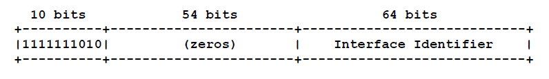
6. Address Mapping — Unicast
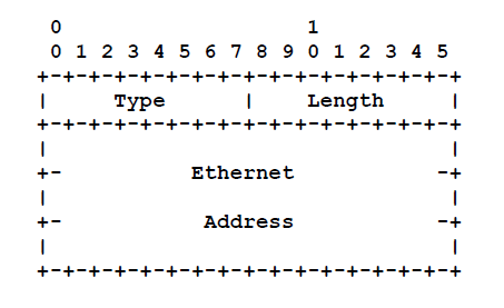 Option fields:
| Type | 1 for Source Link-layer address. 2 for Target Link-layer address. |
| Length | 1 (in units of 8 octets). |
| Ethernet Address | The 48 bit Ethernet IEEE 802 address, in canonical bit order. This is the address the interface currently responds to, and may be different from the built-in address used to derive the Interface Identifier. |

![]()
7. Address Mapping — Multicast

8. Differences From RFC 1972
The following are the functional differences between this specification and RFC 1972.
The Address Token, which was a node’s 48-bit MAC address, is replaced with the Interface Identifier, which is 64 bits in length and based on the EUI-64 format. An IEEE-defined mapping exists from 48-bit MAC addresses to EUI-64 form.
A prefix used for stateless autoconfiguration must now be 64 bits long rather than 80. The link-local prefix is also shortened to 64 bits.
 |  |  |  |  |
 | ") |  |
